Due to the large size of this webpage with about 300 images, it is possible that the browser does not display all images. If that happens enable hardware acceleration, but above all disable Privacy Setting and do not Clear History.
Towards the end of the Construction chapter you will see section preceded with ??? They lack detailed descriptions. All measurements are in millimeters (mm) unless stated otherwise.
Background. I am born in the province of Zuid-Holland, one of the 12 Dutch provinces in The Netherlands. A very large part of that province consist of polders, i.e. land that is below sea level. Not only had the polders to be pumped dry initially, even today they need constant pumping to keep them dry. In the olden days this was done with the Zuid-Holland type Octagon Poldermill (Zuid-Hollandse Achtkant Poldermolen) driven by the wind. In common speech they are also referred to as watermill (watermolen), referring to the function of the mill. However, that is very confusing as the term watermill refers to a mill driven by water power! In the further text I refer to it as the windmill. The Octagon Poldermill I am referring to is a ground sailor (grondzeiler), i.e. the sails are almost touching the ground because the area around the windmill is high and flat enough to get sufficient wind for its operation.
For obvious reasons I built a scale 1:25 windmill to showcase it in the backyard of our first house along a walking & bicycling pathway. Many people stopped to take pictures, and when I happened to be in the yard it often resulted in very interesting conversations as well.
The harsh Canadian winter weather took its toll on the windmill and it required regular maintenance; the last major maintenance was in 2007. And now we are in Oct-2013 and it is time to build a new scale model.
Interesting facts of real Zuid-Holland Octagon Poldermills
The website Vereniging De Hollandsche Molen (association for the preservation of (wind)mills in the Netherlands) provides lots of interesting information. It also provides access to a database of windmills such as De Hoge Molen te Kinderdijk (High Mill in Kinderdijk). The poldermills around Kinderdijk are the most famous Zuid-Holland Octagon Poldermills. Both these website you can switch to English.
For the 840 hectare Nieuw-Lekkerland polder at Kinderdijk they needed to cascade multiple poldermills in order to pump the water from the very low polder into the canal and river Lek. The Hoge Molen is the one at the top. It was built in 1740 as a paddle wheel mill. In 1964 the mill was converted to an auger mill. It is a ground sailor with a sails span of 28.20 meters.
The information of the Hoge Molen is used to determine the measurements of the internal mechanism for the new scale model. The brake wheel features 71 cogs/teeth at a circular pitch of 12.8 cm. That is matched against a cage wheel with 32 rods (the wallower) at the top of the vertical shaft, which has another cage wheel at the bottom with 41 rods at a circular pitch of 12.0 cm. The auger wheel matches that with 47 cogs/teeth, while the auger itself has a diameter of 1.80 meters. The transfer ratio from sails to auger is 1:1.94, one full rotation of the sails equals almost two rotations of the auger.
In comparison, the biggest windmill in the Netherlands is Boezemmolen #6 in Haastrecht (database id 1359) with a sail span of 30.05 meters and featuring a paddle wheel.
Specifications of the new model windmill
The windmill will be 50% larger than the original scale model; hence the ackward scale of 1:16-2/3 or 1:16.67. Simply add 50% to the 1:25 scale measurements! The tower will be about 140 cm (4' 7") tall and the span of the sails is about 240 cm (8' 3").
The original model used ball bearings between tower and cap trundle rings. We were planning to use fixed spaced rollers, but had difficulties to find those. Therefore we use pieces of ¼" (6 mm) thick Ultra High Molecular Weight (UHMW) Polyethylene between the cap and the tower to minimize friction when rotating the cap.
Add an upright shaft with wallower (cage wheel) at the top and cage wheel at the bottom to tranfer power from the brake wheel to the auger wheel. To avoid unequal wear of the cogs/teeth the partnered wheels/gears must not have an exact multiple cogs/teeth of each other.
Pumping water from the "polder" to be done with an auger and using that water to somehow feed a small waterfall back into the "polder". NOTE: The auger (Archimedes screw) will lift up the water using 2 or 3 helices. Augers has a diameter of 100 to 250 cm, an shaft thickness between 30 to 80 cm, and an shaft angle from 22 to 30 degrees. Transfer ratio is 1:2, i.e. one rotation of the sails equates about two rotations of the auger. These rough dimensions still need to be converted to our scale size: we will use 3 helices, auger diameter of 150 mm, auger shaft diameter of 50 mm, and shaft angle of 25 degrees.
Other information you can find under References. In order to follow this project you will have to buy your own drawings as indicated in the links section.
Also note that only the critical structures of tower and cap, and the whole internal gear mechanism are described in detail. The rest is described in much lesser details as those can be found on the drawings and matching documentation.
Pictures
Click on a picture to get a larger picture and then used the back button of the browser to return.
Original windmill at scale 1:25 Tower height 37" (94 cm) Tower base width 20" (51 cm) Sails span 61" (155 cm) Built Oct-1993 to Jun-1994 Total 355 hoursOriginal windmill in 1994Original windmill in 2007 Some repairs were doneOriginal windmill in 2013 Beyond repairOriginal windmill in 20131: Rough stanchions2: Working on first stanchion3: Extension glued to stanchions4: First stanchion shaped and ready to be traced on next one5: All stanchion fronts shaped & sanded6: jig #1 -- 45° jig7: How to use the 45° jig8: 6" draw knife, #11 grain cabinet rasp, #6 grain cabinet rasp9: All stanchion fronts tapered10: Rough trundle rings and tower base boards11: Tower base board marked12: Tower base with corners cut off13: Note front of stanchion being flush with top of tower base14: Slots for stanchions cut out; slots 1 and 2 are finished15: Compass jig16: Tower trundle ring marked17: UHMW strip marked off for "trundle rollers"18: UHMW strip marked19: Setup for routing groove in tower trundle ring20: UHMW strips shaped with holes drilled21: Tower trundle ring with UHMW quarters in place22: Tower trundle ring up close23: Predrilling hole in stanchion top notch24: Tower rundle ring fitted against bottom of stanchion top notch25: Top part of stanchion notch rounded over26: Tower skeleton26a: Stanchions glued in place27: Cap trundle ring marked28: Drilling holes in trundle anchor brackets29: Block of trundle anchor brackets drilled and countersunk30: Trundle anchor brackets31: Inside view of trundle rings32: Outside view of trundle rings33: Joint blocks and centre support34: Joint block, front detail35: Joint block, rear detail36: Routing roman ogee detailing37: Detailing completed38: Tapering jig in use39: Detailing with core box bit40: Joint blocks shaped and glued on cap trundle ring41: Dry fitting short branch, long branch and support block42: Dry fitting wind bolster43: Gluing grid slats 2 to 644: Fitting rafter ring45: Gluing rafter rings (18 clamps!)46: Gluing short branch, long branch and support block47: Keep tail beam aligned48: Custom fitting long brace49: Long brace custom fitted to long branch50: Long brace kept in position with clamp51: Short braces kept in place with clamps52: Tower & cap skeleton finished53: Beautifull white ash54: Outside & inside stocks blanks55: 5x50 mm planks56: 5x7 mm strips57: Square blanks for brake and gears58: Cut out brake and gears with templates59: Test cutting slots for gear teeth60: How to cut teeth slots61: Gear-to-shaft connectors62: Gear-to-shaft connector assembly63: Mark gear-to-shaft connector hole64: Gear-to-shaft connector holes cut65: Test gauge used to check smooth fit in square holes66: Gluing brake wheel core67: Gluing sides to brake wheel core68: Gear wheels ready for teeth mounting; note wax paper and markers inside the holes69: Jig for easy teeth marking70: Start with square end, scribe on back and cut off71: Start with angled end, scribe on back and cut off72: Cutting teeth with scroll saw73: 103plus 20.5 mm teeth74: Tools for gluing teeth: Robson screwdriver to push tooth firmly in position; small screwdriver to apply glue to tooth and tooth slot75: Gear wheel with teeth76: Gear wheel edge sanded, teeth profile marked with precision compass; note 3.5 mm jig77: Peek at real gears78: Gear wheel top view79: Gear wheel side view80: Bearing template81: Upright shaft centre82: Bearing block blanks83: Bearing template on bearing block84: Bearing slot cut85: Bearing blocks finished86: Bearing fitted in slot87: Mounted neck bearing block88: Mounted pin joist89: Mounted upright top bearing block90: Mounted upright thrust bearing block91: Making thrust end of shaft92: Making gear-to-shaft connection93: Cotter (wedge)94: Upper face gear installed on shaft95: Side view upper face gear and wallower gear96: Gears seen from below97: Another view from below; note very tight fit with support block98: Start trundle field frame99: Miter saw setup100: Clamp trundle apron before screwing101: Trundle apron and brace102: Trundle field finished; two centre boards still loose103: Centre front boards in place; holes made for trundle posts104: 10ft 6" PVC pipe...105: ...and the 3ft we needed106: Trundle field raised on 4 short posts107: 4 x 4 trundle posts108: 8 x 2 trundle posts109: Slots cut in trundle posts110: Trundle posts finished111: Tower on trundle field; note anchor positions112: Anchor carriage bolt, trundle field, washer, nut, washer...113: ... tower base, washer, nut114: Auger bearing blocks; note markings for openings in PVC pipe115: Top end auger system116: Bottom end auger system117: Cutting bottom auger support118: Gluing bottom auger support119: Angled support brace120: Front view auger supports121: Rear view auger supports122: Side view auger supports123: Side view of auger system124: Side view of auger system125: Front view of auger system126: Top view of auger system127: Spurwheel gear and auger face gear128: Top view trundle field auger access129: Bottom view trundle field auger access130: Auger access in place131: Looks like this after 175 hours132: Looks like this after 175 hours133: Openings in PVC pipe134: Groove in auger thrust bearing block135: Single coil to determine measurements136: Twine does not really hold hoses in place...137: ...and then all those snakes138: Picture wire looks even worse...139: ...but in the end did the trick140: Three coils around PVC pipe141: Auger face gear, auger top bearing block, auger top end142: Tube auger bottom end143: Tube auger top end144: Tube auger inside auger cup145: Final look at the gears146: Final look at auger system147: Brake pad template traced on oak148: Cut out brake pads149: Sanding brake pad on brake wheel core150: Sanded brake pads151: Brake beam & brake donkey152: Brake donkey glued under long branch next to support block153: Brake donkey glued under long branch next to support block154: Brake pads interconnected with link pieces155: Bottom brake pad with anchor156: Brake beam with all hardware157: Brake catch158: Side view brake system159: Side view brake system160: Brake catch is engaged161: Beautiful piece of red oak162: Glue up for canister163: Making the first cut164: Canister finished165: Canister fitted on shaft166: Canister hardware167: Canister hardware mounted168: Cap rafter templates169: Cap front construction170: Cap rear construction171: Cap rafters laid out172: Detail rafter #3. Outside of rafter not yet trimmed173: Front construction, rafters #1 and #2174: Note shape of pin joist bearing block with Rafter #7 and rear construction175: Extra pieces to form long branch thatch box176: Rafter #2 with long branch thatch box177: Rafters #5 and #2 with ridge-pole178: Spacer blocks glued in place179: Rafter #7 and spacer blocks180: Rafter #6 to #1 and front construction181: Another view182: Rear view183: All rafters placed plus rear construction184: You cannot have enough clamps!!!185: Rafters glued together with end constructions dry fitted186: Rafters glued together with end constructions dry fitted187: See how close the brake wheel is to rafter #2188: Rafters #6 and #7 need cutout for the brake pole189: Removable cap viewed from below190: Extra strips beside thatch box of rafter #2191: Red cedar cutoffs reused192: First part of front corner piece193: Front corner piece completed194: Removable cap construction completed195: Removable cap construction completed196: Cap covered in hardware mesh197: Cap covered in hardware mesh198: Status after 255 hours199: Blank stocks with one bowed 10 mm200: Front and back of stocks marked and ready for cut out201: Front and back of stocks marked and ready for cut out202: Front and back of stocks cut out203: End profile after shaping front and rear of stocks (left is front, top is windboard)204: Marked windboard side for removal with lattice locations marked at the far end205: End profile after shaping windboard side (left is front, top is windboard)206: Smoothing plane 266x40 mm for fine and concave work; Stanley plane 355 x 50 mm for long and straight work207: Note wiggly marks to help guide planing208: End profile after final shaping step (left is front, top is windboard)209: Mass production of 116 >lattice slats210: 16 seam slats, 116 lattice slats, windboards, stocks211: Trimming end of lattice slat212: Jig to drill 13/64" hole under 15° angle (bottom)213: Jig to drill 13/64" hole under 15° angle (top)214: Windboard and slats #1, 11, 17, 23 and 29 glued in place215: Windboards completed216: Lattice slats #1, #9, #22, #26 and #29 glued in place217: Lattice slats #5, #12, #15 and #18 glued in place; front seam slat dry fitted218: 10 mm long and 5 mm round tenon of lattice slats219: Detail of stock with lattice slat #1220: Bottom rear seam slat glued in place221: Detail of curled wire nail222: Middle rear seam slat glued in place223: Remaining 20 lattice slats glued in place224: Remaining 20 lattice slats glued in place225: Lattice work before gluing top front seam slat226: Lattice work before gluing top front seam slat227: Lattice work after gluing top front seam slat228: Sails completed229: Headers and sills cut, ready for dry fitting230: Header shaped and dry fitted on top of temporary stop block231: Sill glued to stanchions; note paper separating it from temporary stop block232: Trundle bench completed233: Louvers for tower thatch boxes glued up234: Most of the headers and sills glued in place235: Thatch box window marked for cut out of panes236: Jig to help with gluing thatch boxes237: Thatch box dry fitted238: Thatch box glued up239: Thatch box dry fitted in place240: Main window241: Fixing access door error242: Access door without trim243: Doors, windows and thatch boxes have now glass244: Doors and windows with lace curtains245: Front beard246: Rear beard247: Trundle wheel hub248: Trundle wheel ring soldered249: Thrundle wheel with spokes250: Trundle wheel in tail beam251: Scribe-stick for marking tower top siding252: Tower base siding with door and window253: Tower base siding with container house door and window254: Tower base siding with shutter (siding removable) and hatch255: First three strips of tower top siding. Note door canapy256: Tower top siding with first thatch box257: Red cedar siding strips; enough for 99 strips258: Discharge water gutter (view under trundle field)259: Removable discharge water gutter260: Discharge water gutter catch under trundle field261: Discharge water gutter catch262: Discharge water gutter (side view)263: Auger gear sticks outside the discharge water gutter264: Tower siding strips up to middle thatch box265: Tower siding strips up to middle thatch box266: Tower siding completed267: Inside look upwards268: Scribe-stick after being used over 350 times269: Ridge cover270: Intake water run (fake)271: 1st coat of fibreglass (cap left)272: 1st coat of fibreglass (cap right)273: Bad spots of fibreglass removed and sanded (cap left)274: Cap after several fibreglass patches and primer275: Cap front side painted276: Cap rear side painted277: Cap trundle ring being painted278: Painting cap trundle ring completed279: Tower upside down for ease of painting280: Tower doors & windows being painted281: Various items painted282: Sails being painted (green is masking tape)283: Screw eyes screwed into sail stock284: Posts dug, concreted and back filled into the ground285: Kneeling for the windmill? No...286: Praying to the windmill? No... Just bolting the tower to the platform287: Just a view288: Just a view289: Canvas for a sail293: Trundle wheel plate294: Maintenance - toe-nailed slat290: Rear view high resolution (738 KB)291: Front view high resolution (678 KB)292: Mighty windmill high resolution (610 KB)
View Video of Working Windmill
Wind coming from between West to North, or straight East are the best for our windmill as the other wind directions are blocked by tall trees, hedges and our own house. Sunday, July 3rd, 2016, was ideal. The wind allowed for several hours of running. Starting at a gentle turning rate and gradually running like a ceiling fan. It proved that the construction is solid, the gears are all working very well, and it smoothed the brake pads a bit too. While running at that high speed the brake stopped it very quickly. And it had enough power to turn the auger mechanism. We were not yet pumping water though.
Mind you that a miller will never run a windmill at such a high speed. The trick is to angle the head (cap) gently into the wind until it runs at the desired speed for pumping water, grinding flour, ect..
Click on this YouTube link https://youtu.be/hn95vu02iLU to watch the Dutch Windmill running at different wind speeds without pumping water.
In July 2017 we were ready to prove that this Dutch Windmill actually can pump water UP with the auger from a container and then let the water flow back into the container. We spliced that video with the above YouTube video and this is the result:
Plans, Drawings, Sketches (mm)
Click on a drawing to get a larger picture and then used the back button of the browser to return.
These pictures show an image of the two drawings and the first page of the 4-page construction manual.
My original windmill was in scale 1:25. I wanted the new windmill to be 50% larger or scale 1:16-2/3 (1:16.67), so my first task was to annotate all measures in red using the new scale by simply adding 50% to the scale 1:25 measurements. Next I had to convert the real measurements of the internal wheels and auger to the scale dimension. Here is where I made a shocking discovery.
I back calculated the 1:25 scale sails span (1560 mm) to the "real" size and came to a sails span of 39 meters! The largest windmill in the Netherlands has "only" a sails span of 30.05 meters. Don't ask me where the draftsman found this Fictional Windmill. In my spreadsheet I converted the measurements from the real windmill into those of the Fictional Windmill and from there back to the various scales.
For example, a human being is 6ft or 1.80 meter in real life. The "fictional" height will be about 2.50 meter, and hence for our scale a height of 150 mm.
Our additional drawings
NOTICE -- When printing the template files with Abode Reader make sure that Page Sizing & Handling is set to Actual Size!!!
Drawing 01, Joint Block Template Three letter size pages that need to be glued together to form the template.
Drawing 02, Joint blocks in relation to cap trundle ring
Drawing 03, Trundle anchor bracket
Drawing 04, Internal gear mechanism
Drawing 04a, Top gear system
Drawing 04b, Bottom gear system
Drawing 05a, Upper face gear template (top)
Drawing 05b, Upper face gear template (bottom)
Drawing 05c, Wallower gear template
Drawing 05d, Spurwheel gear template
Drawing 05e, Auger face gear template
Drawing 06, Tooth profiling
Drawing 07, Bearing blocks
Drawing 08, Canister (poll end)
Drawing 09, Tower layout
Drawing 10, Trundle field using red cedar
Drawing 11, 45 degree brake pad
Drawing 12, Cap rafter profile templates (6 pages) Six letter size pages that need to be glued together to form the template.
Drawing 13, End profile of sail stocks.
Materials List in mm for scale 1:16-2/3 (1:16.67)
Here is the detailed materials list. We are using white ash, red oak, Western red cedar and various thicknesses of plywood. All sizes are in mm (millimeter) unless otherwise indicated.
The measurements in this list are the main outside sizes. Most pieces need additional shaping according to the drawing.
In order to keep friction to a minimum we use stainless steel deep-grove (CONRAD) ball bearings. The advantage of these bearings is that they can accept both radial load (perpendicular on the shaft) and thrust load (in the direction of the shaft). Huge disadvantage is the cost; we paid Can$ 382.00 for six ball bearings.
We also use pieces of 1/4" (6 mm) thick UHMW Polyethylene between the cap and the tower to minimize friction when rotating the cap.
The Dutch name of part numbers 1 to 49 are taken from the drawings and construction manual. Dutch names of the other parts and all the English names have been obtained from various sources or are purely descriptive. Don't hesitate to contact us when you happen to have a more correct name.
Secondly, thicknesses in bold (e.g. 41) are calculated thicknesses according to the original drawing. However, when there is little or no impact on strength and/or appearance we rounded those to the nearest standard imperial units; like 36 mm becomes 1-1/2" (38 mm), 41 mm becomes 1-1/2" (38 mm), etc.
*) Original drawings and our added drawings are all in millimeters. Due to the fact that all wood measurements and other hardware are in imperial units you will encounter a mixed use of units; we do apologize for that.
Tower (Romp)
ref #
qt
description
length/ height (mm)
width (mm)
thickness (mm) *)
colour, suggested material, comments
0
1 6 2 2 2 2 8
trundle field (krui veld) top boards
brace apron boards
1,620 1,620 1,453 1,173 894 1,544 693
1,620 5-1/2"
5-1/2" 5-1/2"
1-1/2"
1-1/2" 1-1/2"
grey/brown; 2" x 6" red cedar
angled brace fitted when mounting auger system!
1
8
stanchion (stijl)
1,061
104
36
red oak
2
1
tower base (grondplaat)
743
743
19
grey; 3/4" plywood
4
1
tower trundle ring (onderring)
504 Ø
19
brown; 3/4" plywood; inside opening 432 Ø; contains the rolls
26
8
thatch boxes (rietkisten)
144
41
yellow; position low box at 270 to 414, middle box at 455 to 599, top box at 756 to 909 above tower base; recessed 27 following stanchion angle; window height 77; louvers 90 total height
29a
1
intake water run (achterwaterloop)
495
180/95
grey & white
29b
1
discharge water run (voorwaterloop)
522
95
grey & white
8
siding tower base
200
320
white; tapers 3.5 degrees to the top; custom fit to stanchion centre edge and accomodate the various doors and windows
30
2
access door (toegangsdeur)
258
108
light brown & yellow; top at 257, canopy 171 wide; 11 mm recessed at top header; door frame 5 x 7 white ash; door step 5 x 10 white ash; canapy 120 x 170 1.5mm Finnish plywood
31
1
container housing door (pothuis, waterloop deur)
180
108
brown; 7 mm recessed at top; door frame 5 x 7 white ash; door step 5 x 10 white ash
34
2
window (venster)
126
158
yellow; 27 mm recessed at top
35
16
trundle post (krui-paal)
65
29
29
brown; red oak
38
1
shutter (blind)
90
180
dark green; half circle; on outside of surface; whole surface removable
44
1
hatch (luik)
117
95
brown; rectangular; on outside of surface; trimmed with 5 x 5 mm white ash
176
siding tower top
320
1-1/2
thatch colour; strips sawn at 15 degree angle from 2" x 6" (1-1/2" x 5-1/2" nominal) red cedar lumber; rough surface is okay to give rough final look
49
2
water run gates (waterloophekken)
white
4
UHMW quarter (rol)
custom made from UHMW Polyethylene 24" x 4" x 1/4"
6
aluminum angled brackets
1-1/4" x 7/16"
3/4"
1/8"
custom made
42
1 pkg of 100 flat head screws
5/8"
#6
(Lee Valley 01Z32.05) 6 for each UHMW quarter (24) 3 for each angled bracket (18)
8
flat-head flooring screws
2"
#8
To attach tower trundle ring to stanchions
76
flat-head Spee-Drill deck screws
3"
#8
To put trundle field together
4
carriage bolts
3"
3/8"
To anchor tower to trundle field
8
nuts
3/8"
To anchor tower to trundle field
12
washers
1/2"
3/8"
To anchor tower to trundle field
1
Clear Marine Silicone 2.8 fl.oz.
To glue glass to back of window openings
thin glass
460
250
glass to act as window panes
4
post
72"
6"
6"
Pressure treated wood; length to match depth of holes and height above sloping ground surface, and trimmed to same height to support a levelled trundle field platform
Cap (Kap)
ref #
qt
description
length/ height (mm)
width (mm)
thickness (mm) *)
colour, suggested material, comments
3
1
cap trundle ring (overring)
504 Ø
19
brown; 3/4" plywood; inside opening 432 Ø; contains outside groove to hold trundle anchor brackets
5
1
long branch (lange spruit)
1080
41
41
yellow; red oak
6
1
short branch (korte spruit)
540
41
41
yellow; red oak
7
2
joint block (voeghout)
610
80
41
brown; red oak, needs shaping
8
1
support block (steunder)
198
41
41
brown; red oak
9
1
wind bolster (windpeluw)
270
72
63
white; red oak
10
1
tail beam (startbalk)
1193
45
45
bruin; red oak, tapered
11
2
long brace (lange schoor)
1170
23
23
yellow; red oak
12
2
short brace (korte schoor)
780
23
23
yellow; red oak
16
1
neck bearing block (halslager)
see Internal Mechanism
17
1
pin joist (penbalk)
see Internal Mechanism
18
1
brake wheel (vangwiel)
see Internal Mechanism
19
1
windshaft (wind as)
see Internal Mechanism
20
1
brake beam (vangbalk)
328
52
36
made extra heavy; red oak
27
1
brake donkey (ezel)
270
38
38
made extra heavy; red oak
1
carriage bold
110
M6
with 2 O-rings, 2 nuts; to attached brake beam to brake donkey
6
brake pad
96
27
24
45° arc segment; inside R=110, outside R=125; red oak
5
brake pad link
50
22
0.3
brass shim stock; to interconnect brake pads
10
pan head screw
1/2"
#6
To connect brass shims to brake pads
2
screw eye
1/2"
#6
One on each end of assembled brake pads
3
screw eye
3/4"
#8
One on top of brake beam connects to top brake pad via chain link On in side of joint block connects to bottom brake pad via brass rod One on free end of brake beam to connect to brake pole via rope
1
brass rod
8"
1/8"
Connects bottom brake pad to joint block
1
Jack chain
10"
Connects top brake pad to brake beam
21
1
brake catch (sabelijzer)
12"
2"
1/8"
Needs shaping; mild steel
1
brake catch anchor pin (screw eye)
1-5/8"
#10
Screwed into side of brake beam (head removed)
1
brake catch header block
2"
1-1/2"
3/4"
Shaped and glued to inside of joint block so that free hanging brake catch lines up with side of brake beam
1
pan head screw
3/4"
#8
To attach brake catch to its header block
22
1
brake pole (vangstok)
520
3/8" Ø
white; hemlock; 175 mm inside, 345 mm outside; use 1/8" brass rod as pivot point, hold brass rod in place with hanging down picture frame turn
23
1
trundle bench (krui-bank)
171
104
brown; white ash; (2) beams 171 x 10 x 15; (3) slats 104 x 22 x 5; (2) slats 62 x 22 x 5 (4) panhead screw #8 7/8" (1) brass rod 1/8" 200 mm bended (4) brass round head nails 1/2"
24
1
trundle wheel (krui-rad)
green & white axle L:270, T:18, end 13 head L:45, T:40 (octagon) spoke L:130, T:9 large ring (brass) D:210, T:5 small ring (brass) D:120, T:5
25
14
grid slat (roosterhouten)
130
22
10
bruin; red oak, approx. 1550 mm total length, custom fitted
28
2
rafter ring (spantring)
563
171
10
brown; 1/2" plywood, 600 x 400 mm, shaped
32
1
front beard (voorbaard)
240
110
1.5
white; 1.5 mm Finnish plywood
33
1
back beard (achterbaard)
310
70
1.5
white; 1.5 mm Finnish plywood
45
1
cap (kap)
thatch brown/grey
46
1
cap front construction (voorkeuvelend)
235
113
3/4"
yellow & green; 3/4" plywood; split & shape
48
1
storm shield (stormschild)
220
180
3/4"
brown; 3/4" plywood; split & shape
47
1
cap rear construction (achterkeuvelend)
320
83
1/4"
yellow & green; 1/4" plywood; custom fit and requires oak for overhead beam and stiles, and trim for window
1
fixed bottom slat cap rear
330
1/2"
1/2"
brown; red oak
1
wolf roof (wolfsdak)
280
200
3/4"
thatch brown/grey; 3/4" plywood; shape
7
cap rafter (spant)
1/2"
1/2" plywood, all different shapes; total size 42" x 35"
1
ridge-pole (nokbalk)
420
25
15
white ash; custom fit
1
ridge cover
400
45
20
left-over wood, custom fit
2
long branch thatch box side (koker)
167
133
1/2"
yellow & green; 1/2" birch plywood about 42" x 35"; the other side is part of cap rafter #2; louver L:50, W:24, recessed 25, angled following cap roof line
2
long branch thatch box top
121
43
1/2"
yellow & green; 1/2" birch plywood; connect side to cap rafter #2
16
spacer block
1200
50
18
white ash or aspen; custom fit between rafters and end constructions; total of 2 lengths of about 600 will do
6
corner filler block
120
60
35
cut offs from 6" x 2" red cedar
14
reed-lath (rietlat)
720
7
5
white ash; optional, see construction details
1
flag pole
360
3/8"
white
9
pan head screws
1-1/2"
#10
Internal Mechanism (Interne Aandrijf Mechanisme)
ref #
qt
description
length/ height (mm)
width (mm)
thickness (mm) *)
colour, suggested material, comments
19
1
windshaft (wind as)
580
35 Ø
1-3/8" hardwood dowel (24")
16
1
neck bearing block (halslager)
200
104
45
has 35-62-14 bearing embedded; mounted on wind bolster
17
1
pin joist (penbalk)
324
80
41
has 30-55-13 bearing embedded; mounted on joint blocks
2 screws to keep each ball bearing in place on block
12
washer
3/8"
#6
2 washers to keep each ball bearing in place on block
10
flat-head Spee-Drill deck screws
3"
#8
To attach angled brace under trundle field
4
flat-head Spee-Drill deck screws
2-1/2"
#8
To attach support under trundle field
left-over cedar
To construct auger system supports (see construction details)
2
flat metal latch
260
1"
1/8"
To hold PVC pipe snug against supports
5
biscuit
#20
(2) To connect auger bottom support boards (3) To connect auger access panel boards
1
brass nail
2"
To hold PVC pipe in place
2
finishing nail
2"
To hold auger access panel in place
Auger System -- option 1 with 3 helixes
T.B.D.
Auger System -- option 2 with 3 parallel tubes
1
PVC pipe
650
4" Ø
Base to wind hoses on
3
Gardena heavy duty 5-ply hose
5,000
5/8" Ø
cut 50ft hose into approximatly three equal length pieces
2
auger end
o:102 Ø
7/8"
red oak
picture wire
6 ft
For tying about three loops of the hose ends to the base
8
auger-end-to-shaft connector
100
17.5
17.5
11/16" hemlock cove moulding 4 for each auger end
4
cotter (wedge)
40
7
5
to lock auger end from sliding 4 for each auger end
6
pan head screw
3/4"
#8
(6) To attach auger ends inside 4" PVC pipe
8
finishing nail
1"
1/16"
nail connector to shaft 1 for each auger end shaft connector
4
finishing nail
3/4"
1/16"
nail cotter to shaft 1 for each cotter
Sails (Wiekenkruis)
ref #
qt
description
length/ height (mm)
width (mm)
thickness (mm) *)
colour, suggested material, comments
13
1
outside stock (middling) (buitenroede)
2340
41
41
light brown
14
1
inside stock (middling) (binnenroede)
2340
63
41
light brown
15
1
canister (poll end) (askop)
123
123
123
white; Different design & size versus original drawing
36
1
canister catch (meenemer)
red; not used in this scale
37
1
cover plate (sluitplaat)
red; in this scale pure decorative
4
main L-bracket
150
3/4"
3/4"
(1) aluminum angle bar 1/8 x 3/4 x 36"
4
stock L-bracket
68
3/4"
3/4"
5
main threaded rod
150
1/4"-20
black; (3) 2ft screw rod
4
inside stock threaded rod
70
1/4"-20
4
outside stock threaded rod
130
1/4"-20
26
lock nut
1/4"-20
two for each rod
2
anchor pin (panhead screw)
3/4"
#8
keep two main L-brackets in place on canister
39
116
lattice slat (heklatten)
163
7
5
light brown; 153 visible & 10 embedded
40
4
front seam slat (voorzoom)
1028
7
5
wit
41
8
rear seam slat (achterzoom)
1028
7
5
light brown
42
4
seam slat (zoomlat)
1028
7
5
wit
43
4
windboard (windbord)
1028
45 to 29
1.5
wit; Finnish-birch plywood
60
windboard slat (windbord lat)
55
7
5
wit; from 45 to 29 visible & 10 embedded
420
wire nails
5/8"
18 gauge
to strengthen attaching seam slats to lattice and windboard slats
1
dowel pin
1-1/4"
1/4"
keep inside and outside stocks centered on each other
4
canvas (nylon)
1060
185
20 mm all around for seem for sewn final size of 1015 x 145
64
eyelet
4Ø
8 eyelets bottom edge and 8 eyelets at top edge of each of the four canvasses
36
screw eye
5Ø
9 screw eyes per sail side
4
rope
1400
3
cotton
Miscellaneous Hardware
ref #
qt
description
length/ height (mm)
width (mm)
thickness (mm) *)
colour, suggested material, comments
Titebond III Ultimate Wood Glue
Sanding sealer mix
A 50/50 mix of Lacquer Sanding Sealer and Lacquer Thinner. WARNING -- Extremely volatile/flamable; mix and apply outside (non-freezing weather) and away from flame and sparks !!! Let application dry for at least one hour before taking inside.
Clear BriWax
Mixture of Beeswax and Carnauba wax
2
Fibreglass mat, 8 sqft
Brand name Bondo; available in auto parts shops or marine supply shop
2
Fibreglass resin, 852 ml
Brand see above; comes with enough hardener for the whole can.
Green door frames, cap front/rear constructions, storm shield, trundle wheel
WeatherOne, sheer exposure
Light Brown joint/support blocks, tail beam, various cap pieces, outside/inside stocks
4
treated post
8ft
6"
6"
to support the platform
10
25kg bag concrete
Raw Material (inches)
Approximate list of raw material bought for this project. Where possible I use leftover material from previous projects too; those are not listed here.
4 pcs of 7ft -- 2" x 4" (1-1/2" x 3-1/2") red oak
stanchions
5ft & 7ft -- 2" x 4" (1-1/2" x 3-1/2") red oak
joint blocks, support, tail beam
5ft -- 1" x 5" (3/4" x 4-1/2") red oak
tail beam
6-1/2ft -- 2" x 6" (1-1/2" x 5-1/2") red oak
long & short braces, wind bolster
left overs from above
bearing blocks, canister
1 pc 5ft x 5ft -- 3/4" Baltic birch plywood (furniture quality)
10 pcs of 10ft 2" x 6" S4S red cedar (nominal 1-1/2" x 5-1/2")
trundle field and auger system
10ft 6" PVC pipe
auger system
10ft 4" PVC pipe
auger system
50ft 5/8" Gardena heavy duty 5-ply hose
auger system
Brass shim, 6 samplers (Lee Valley 27K07.50)
brake pad links, canister fitting, etc.
Welded Hardware Mesh 1/4"x1/4" 2ft x 5ft
To cover removable cap and form a basis for epoxy roofing material
1.5mm 3ply Finnish-Birch water resistant plywood 25"x 25" (Lee Valley 03A10.04)
Attached against seam slats, lattice slats and windboard slats
4 pcs of 8ft posts 6" x 6"
As foundation to anchor platform
10 bags concrete
To pour around posts as foundation to anchor platform
Required Tools
Power tools -- circle saw, table saw, sliding compound miter saw, band saw, scroll saw, planer, jointer, plunge router, stationary disc sander (large), stationary belt sander (small), drill press, hand drill
Hand tools -- tape measure, square, marking gauge, chisels, gouges, sanding block, clamps, 8" cabinet rasp (grain 11), fine wood file, keyhole or compass saw, hack saw, metal file, heavy duty stapler, metal sheers, hand planes
Jigs -- self-made; see construction details
Router bits -- 1/2" straight cutter (Lee Valley 16J04.08), 1/8" slot bit 5/16" deep (Lee Valley 16J83.12), 1-1/2" roman ogee bit height 13/16" radius 1/4" (Canwood R1302), 5/8" diameter core box bit (Lee Valley 16J15.55), 31/64" plywood bit 3/4" long (Lee Valley 16J04.81)
Miscellaneous -- #6 HSS drill/countersink (Lee Valley 66J40.06), set of HSS brad-point drill bits, 1-1/2" sanding drums, sand paper #220, Titebound III Ultimate Wood Glue, clamps (at least 9), paste glue stick (e.g. Ross Stick, Elmer's, UHU), scroll saw wood blades RG#5, RG#7 and RG#9, Milwaukee hole saws 1-1/8" (29 mm), 1-1/4" (32 mm), 1-3/8" (35 mm), 1-1/2" (38 mm), cutting fluid for metal, Faber Castell black soft 9201-099*** (for marking surfaces and edges while planing), clothespins
Construction
All measurements are in centimeters while all wood measurements in the shop are in inches (1 inches = 25.4 mm). I recommend to cut, shape and sand all pieces and dry-fit them together with clamps.
It is assumed that you are familiar with all your machines and jigs. Check out the Workworking Tips section for basic machining tips of rough sawn wood.
FINAL WARNING -- All construction measurements are for the scale 1:16-2/3 (1:16.67) model !!!
28-Jan-2014 to 12-Apr-2014 -- The first saw dust was made. Prior to the start lots of time was spent on extra design work, drawings and web site. Completed the critical parts of the tower and cap which took about 80 hours.
3-Feb-2015 to 18-May-2015 -- After the summer and fall I ended up looking after my wife (broken wrist) and the household before I could resumed again. This time the trundle field, internal mechanisms and auger system got all the attention. That brought me to a total of 187 hours. On rainy summer days I did some work on the model though.
12-Dec-2015 -- Prior to this start date I did some work on the brake mechanism on rainy summer days.
17-Apr-2016 -- Actual construction completed after 457 hours! Start of painting and finishing touches.
27-Jun-2016 -- Trundle field platform placed on four digged in posts, and the windmill placed and anchored on top of the platform. Official opening has to wait until the name plate(s) have been carved.
To give an idea of the required construction and finishing time:
Activity
hours
Tower, trundle field (Romp)
174¾
Cap, removable cap (Kap)
124½
Internal mechanism (Interne Mechanisme)
90¾
Canister, Sails (Wiekenkruis)
74
Fibreglass cap, Painting
85½
Outside installation, digging posts (approximate)
20
Total time
569½
The project was considered completed on 27-Jun-2017, with the exception of this webpage.
Terminology & Overview
This is an overview how things fits together.
Tower - The eight-sided tower consists of eight stanchions resting on an eight-sided base and held together at the top by the tower trundle ring. The tower will be anchored to the trundle field that has 16 trundle posts that help turning the cap and sails into the wind direction.
Internal Mechanics - Consist of the windshaft with brake wheel and upper face gear. The face gear drives the upright shaft with the wallower gear at the top and the spurwheel at the bottom. The spurwheel drives the auger gear that is connected to the auger mechanism. The triple helix auger rests in a cup and moves the water up. All shafts are fitted with ball bearings to minimize friction.
Cap - The cap is built on top of the cap trundle ring with two joint blocks running from front to back. From front to back the wind bolster, long branch and short branch sits on top of the joint blocks. The wind bolster is key for supporting the windshaft and sails. The long and short branches provide support for the tail beam that runs down at an angle from the back. The tail beam is used to turn the cap and sails into the wind direction. To be able to reach the internal mechanism for possible maintenance at a later date the cap has to be removable. The cap trundle ring sits on top of the tower trandle ring. The two trundle rings are equiped with UHMW (Ultra High Molecular Weight) Polyethylene to minimize the friction when rotating the cap.
Sails - The front of the wind shaft has a canister, or head, that connects the two stocks (sails) to the wind shaft.
Tower (stanchions)
It is important to ensure that the stanchions, tower base and trundle rings are as accurate as possible. That is why we spend lots of time making them as it is the basis of the whole windmill.
We start with the four 7ft long red oak 2" x 4" pieces (nominal 1-1/2" by 3-1/3"), and cut them in half to 3-1/2ft length (picture 1). Check the grain and mark what will be the bottom and the outside edge; mind you that the outside edge needs lots of machining! We will have to glue a piece of red oak to the front of the stanchions so it is important that front surfaces are flat; we made a 1/64" pass on the jointer.
At this point you can make a template for the stanchion, but we decided to draw the outline on the first stanchion. Measure/calculate the width of the stanchion at about 40 mm intervals and then connect the marked points with a straight line; you will be amazed at the resulting curve. The tower trundle ring will rest in the top notch of the stanchions. The cap trundle ring will rotate around the stanchions on top of the tower trundle. The vertical height of the notch is 36 mm according to the drawing. We use 3/4" Baltic birch plywood which is actually 11/16" thick. Instead of ball bearings or rollers we use UHMW polyethylene that will extend 1/8" above the tower trundle ring. So this adds up to 11/16 + 1/8 + 11/16 = 1 1/2" = 38 mm. In other words the top of the cap trundle ring will be 2 mm above the top of the stanchions which is enough free space for unobstructed rotation of the cap.
As already mentioned earlier the width of the red oak is 3-1/2" (88 mm). We need however a width of 104 mm at the widest part of the stanchion, but only over a short length that we will call the "nose". We set the table saw fence at 2-1/2", and with the backside of the marked stanchion against the fence we rip a piece of 25 to 26" (picture 2). The ripped off piece we cut into 8 pieces of about 3" long and these we glue on the front side of the stanchions where the extra width is needed (picture 3). Now we can also finish drawing the front curve on the first stanchion.
With the mitter saw we trim the ends at 8 degrees. Raise the table saw blade to maximum height and set the fence at 77 mm, i.e. the width of the bottom section of the stanchion. With the backside of the stanchion against the fence we rip until just before the protrution (nose). For the rest of the cuts we use the bandsaw. Make sure to cut very accurate -- I like to cut off half the line width! With the bandsaw finish the cut at the bottom and the small cut under the protrusion (nose). We continue with the bandsaw to cut off the inside sliver at the top, and make the vertical cut of the top notch. Starting at the bottom cut the arched front. Transfer the horizontal marking of the top notch to the reverse side and then we cut the notch out. Clean up corners with a chisel, file rasp and/or sandpaper. Use a 1-1/2" drumsander to smooth the front arch and then use a sanding block with 220 grid sandpaper to further smooth the whole front of the stanchion. Now the first stanchion is ready to be traced onto the other seven stanchions (picture 4) which can then be machined like the first stanchion (picture 5). Try to keep the cut off of the front arch in one piece so that those can be used later on.
With a marking gauge we score the centre of the stanchion fronts; that is at 19 mm from the edge. Use a pencil to trace the score marks so that they are more visible. We do the same on both sides of each stanchion at 19 * tan(22.5) = 8 mm. The 22.5° sliver between the centre and edge we have to take off. We have two options.
Option 1 -- If you don't have a bandsaw or a bandsaw with tilting table then you may consider making a jig first. We just happen to have a piece of 18" by 3" by 1½". Make sure the surfaces are parallel and square to each other. With the table saw blade set at 22.5° we make a deep cut on the narrow edges with the piece flat on the surface of the table. We lower the blade a bit, and with the narrow edge on the table surface we relieve the triangular cut out (picture 6). We show how to use the jig in (picture 7). Note that we numbered the stanchions such that when we look down onto the windmill the stanchions are numbered clockwise 1 to 8. So in this case stanchions 1 and 2 share half of their front to provide the basis of one side of the tower. With the help of the 45° jig the 22.5° edges can now be finished using various tools like a draw knife, cabinet rasps, sandpaper wrapped around a long flat stick, etc., (picture 8). Keep an eye on the markings!
Option 2 -- The tapering of the stanchion fronts is best done with the bandsaw at 22.5°. With the good side of the stanchion slanted up we cut off the triangle just shy of the side marking. If everything is done correctly then the centre marking should remain visible (picture 9). Clean up the wood under the nose with a crosscut saw and chisel. Finish with a sanding block with 220 grid sandpaper. The most important part is that arch curve is smooth and the bottom section of the stanchions is straight. Sanding marks are okay as the whole tower will be covered later anyway.
Whatever method we use, the angled front of the stanchions will never be perfect. First of all the stanchions are angled backward at 8°, the top part of the stanchions are arched and finally the gap between two adjacent stanchions is narrower at the top. Once the tower base, stanchions and tower trundle ring have been put together can we properly verify the stanchion edges and make possible corrections.
Tower (base)
Next we work on the tower base and the trundle rings for the tower and cap. For that we use a 5 by 5 ft piece of 3/4" thick Baltic birch plywood. On one square corner mark off a 750 by 750 mm square. On another corner mark off a 520 x 1040 mm rectangular piece. We use a circular saw to roughly cut out the marked pieces. Next use the table saw to cut a perfect square tower base of exactly 743 x 743 mm. From the other piece cut two perfect squares of 510 x 510 mm. Having these perfect square pieces allows us to accurately mark them for further cutting (picture 10).
Starting with the 743 x 743 mm board mark the centre of each edge at 371.5 mm from the corners. Using a straight edge, clamped to the board, draw lines from one edge centre to the opposite edge centre. Where the two lines cross is the centre of the tower base. Using the same procedure draw diagonal lines from between opposite corners. The octagon sides are 743 * tan(22.5) = 308 mm, hence mark off 154 mm to the left and right of each edge centre. Draw lines between the two adjacent marks of each board corner; the distance should be 308 mm also! NOTE: a quick way, provided that the board is perfectly 743 mm square, is to measure off 217.5 mm along all edges from the board corners; afterall 2 * 217.5 + 308 = 743 mm.
Next draw an approximately 100 mm long centre line for each stanchion from each octagon corner to the opposite one. The stanchions are 38 mm wide, so mark off 19 mm on either side of the stanchion centre lines and connect the opposite markers with an approximately 100 mm line. Finally, draw a line perpendicular to the centre line at 77 mm (the depth of the stanchion) from the octagon corners (picture 11).
Now we need to cut off the four corners and the easiest way we could think off was to use the bandsaw while supporting the large tower base with our own custom made roller stand (picture 12). Use some 220 grid sandpaper to smooth the saw marks. Next we used the bandsaw again the cut in the sides of the stanchion slots. Using a hand scroll saw make the cross cut, but stay away about 3 mm from the marked depth because the stanchion slot angles outwards at an 8° angle like the stanchion. Number the slots clockwise from 1 to 8; the rear is between 1 and 8 and hence the front between 4 and 5. Finally finish the three sides of the stanchions holes with a 11 grain cabinet rasp while custom fitting each stanchion to its own stanchion slot (pictures 13 & 14).
Tower (trundle ring and "rollers")
Starting with one 510 x 510 mm board first mark the centre on each side at 255 from the corners. Using a straight edge, draw lines from one edge centre to the opposite edge centre. Where the two lines cross is the centre of the tower rundle ring. Using the same procedure draw diagonal lines between opposite corners. Now we need a large compass to draw the outside and inside circles. We don't have a fancy compass for those size radii so it is jig time again. First mark on the board starting at the centre the radii of the outside circle at 252 mm and of the inside circle at 216 mm. Add two more radius marks at 234 mm minus 1/4" and 234 mm plus 1/4"; these represent the 1/2" wide groove we need for the UHMW strips. Using a piece of left over red oak 12" long and 1/2" wide and 1/4" thick we drill a little pilot hole at one end and put a finishing nail through it. Place the tip of the finishing nail at the circle centre and tap it in. Copy the marks of the four circle radii onto the edge and on top of the compass jig and cut V-grooves on the edge of the compass where the bottom of the V is the exact radius. With a sharp pencil pushed into the bottom of the V-groove draw the inside and outside circles (picture 15). Next we have to mark where the top of the stanchions are meeting the trundle ring. The stanchions are 38 mm wide, so mark off 19 mm on either side of the stanchion centre lines and connect the opposite markers with a line between the two circles (picture 16). Number stanchion locations clockwise from 1 to 8; the rear is between 1 and 8 and hence the front between 4 and 5.
We were planning to use fixed spaced rollers, but had difficulties finding those. Therefore we use pieces of 1/4" (actually 7 mm) thick UHMW Polyethylene between the cap and the tower to minimize friction when rotating the cap. We start with a piece of 24" x 4" UHMW and mark a line in the centre at 12". On each section mark the centre at 6". Line up the 6" centre against an edge centre of the board. Line up the centre nail of the compass on the centre line of the board such that the smaller inside circle V-groove touches the edge of the UHMW strip and then tap in the compass nail. Using a sharp awl scratch both inside circles onto the UHMW strip for the first quarter circle. Move the compass centre and scratch the second quarter circle. Slide the strip over, align and scratch two more quarter circles. We then traced the scratched circles with a fine tipped permanent marker (pictures 17 & 18).
Time to cut the 1/2" groove into the tower trundle ring. We use a plunge router with a 1/2" straight cut bit. We have already a simple jig made of a piece of plywood onto which we can mount the plunge router. Set the plunge depth such that the UHMW material will protrude about 3 mm above the trundle board. Next, lower the router so the bit is flush with the bottom of the jig, turn everything upside down and measure off 234 mm (centre of the groove) from the centre of the router bit to a convenient spot on the jig. Drill a 1/4" hole on the marked spot on the jig and a 1/4" hole in the centre of the trundle board. Using a 1/4" bolt and two nuts attach the jig to the board making sure the jig is tight to the board, but can still be rotated (picture 19). Route the groove in two passes.
Use the bandsaw to cut out the outer circle. Using a stationary disc sander with perpendicular table, sand the outside circle to a smooth circle. Use the bandsaw to cut the UHMW strip in half and then cut out the four quarter strips. Using stationary disc sander and 1-1/2" drumsander make the UHMW quarters fit in the trundle ring groove. Fit the quaters between stanchions 1-3, 3-5, 5-7 and 7-1, and ensure that all the edges are eased over. In the centre of each quarter drill a 5/16" hole -- the size of the flooring screw head -- so that we can reach the screws for stanchions 2, 4, 6 and 8. Drill 9/64" holes in the centre of the groove at the centre where the stanchions are coming and countersink them. Finally drill six evenly spaced holes in the UHMC quarters using the #6 HSS drill/countersink such that the #6 flat-head screw sticks out about 3/8" (picture 20).
Drill a pilot hole in the trundle board close to the inside circle. Use a hand scroll saw to cut out the inside circle. Use a 1-1/2" drumsander to smooth the inside circle (picture 21 & 22).
Clamp stanchion #1 in a vise and position the tower trundle ring on the top notch against the bottom while lining up with the markings for stanchion #1. That is the final position of the trundle ring, so we now can drill a 9/64" pilot hole, about 1-1/2" deep, into the stanchion using the trundle ring hole as a template (picture 23). Of course the cap trundle ring is the same size and sits on top of the tower trundle ring and when the cap trundle ring rotates it will scrape against the side edges of the stanchion notch. Therefore we use a grain 11 cabinet rasp to round over the notch edges above the tower trundle ring about 1 mm while using the trundle ring as a template. In this way the cap trundle ring will have a 1 mm free play all way around (pictures 24 & 25).
Before putting the tower skeleton together we first have to make six evenly spaced marks along the outside of the trundle ring to indicate where the six trundle ring brackets are coming. Start with a mark exactly between stanchions 1 and 8 and a mark exactly between stanchions 4 and 5. Next, on both sides of these two marks measure off 252 mm (the radius of the outside circle). Transfer the six marks to the outside of the trundle ring and only then gently sand the top of the trundle ring and ease over the edges. Place the tower base on the ground. Using the 2" flooring screws attach the tower trundle ring to the stanchions while placing the stanchions in their appropriate slots in the tower base. Don't glue the stanchions to the tower base as we still need to do some work on the tower base when we install the auger later. Place the UHMW quarters properly in the groove of the trundle, making sure that the centre hole lines up with the head of the flooring screw. Predrill 3/32" holes for the 5/8" flat head #6 screws and screw the UHMW quarters in place (picture 26).
After the cap trundle ring and the trundle anchor brackets are made, and are fitting properly (see Cap construction), we recommend to glue the stanchions to the tower trundle ring and the tower base. Place the tower base on a flat surface with a pieces of paper under each slot. Glue the stanchions in pairs (1-5, 3-7, 2-6, 4-8), tighten the screw through the tower trundle ring, use a strap to hold all stanchions together (not too tight as that might deform the structure), and let each pair dry for at least an hour before doing the next pair (picture 26a). After that turn the tower upside down, scrap off the paper and sand the bottom of the stanchions flush with the tower bottom.
This ends the critical construction part of the tower. We now continue with the cap trundle ring and the angled brackets, and continue with more tower work later.
Cap (trundle ring)
Using the other 510 x 510 mm board first mark the centre on each side at 255 from the corners. Using a straight edge, draw lines from one edge centre to the opposite edge centre. Where the two lines cross is the centre of the cap rundle ring. Using the same procedure draw diagonal lines from between opposite corners. Using the same compass as for the tower trundle ring draw the circles with radii 252 mm and 216 mm. For ease of marking declare one edge to be the rear and the oppsite edge the front. The seven grid slats radiate out on each side from the joint blocks and at angle of 15° to each other. From the side centre mark off on both sides three sections of 66 mm on the outside circle; close enough for 15°. Connect with a line the opposite grid slat centre (picture 27).
With the bandsaw cut out the outer circle. Using a stationary disc sander with perpendicular table sand the outside circle to a smooth circle. Make sure that the outside circle is about 1 mm smaller in diameter compared to the tower trundle ring! Next we need to create a 3/16" groove on the outside where the angled brackets of the tower trundle ring can slide in. We use a 5/16" deep 1/8" wide slot router bit in the router table. The groove should be positioned about 1/16" below the side centre up to 1/8" above the side centre which take two passes with the trundle board flat on the table.
Same as with the tower trundle ring, drill a pilot hole in the trundle board close to the inside circle. Use a hand scroll saw to cut-out the inside circle. Use a 1-1/2" drumsander to smooth the inside circle. NOTE: save the inside cut out as we can use that for the inside of the brake wheel later. Fit the cap trundle ring on top of the skeleton tower. Make sure that it has 1 to 2 mmm free play all the way around. For smooth rotation sand the bottom of cap trundle ring. If you happen to have a leftover piece of paraffin candle (from Gouda!) rub it on the bottom of the cap trundle ring and the exposed part of the stanchion notches.
The cap trundle ring will eventually be held onto the tower with six angled aluminum brackets which are screwed to the tower trundle ring. The closest we could find was a 3ft long L-shaped aluminum rod. 1/8" thick and sharp angled, which is good, with 2" sides. 3ft is an overkill as we needed only six pieces of approximately 3/4" wide with a total length of 4-1/2". Drawing 03 shows the dimensions of the trundle anchor brackets. For the time being leave the six brackets in one piece ensuring a little extra length to allow for the thickness of the hack saw blade. First trim the sides to the proper width with the hack saw. Next mark where the screw holes are coming and centre punch the screw hole centre. Use a 2 mm drill bit to predrill the holes using some cutting fluid. Next drill the final size with a 4 mm drill again using cutting fluid (picture 28). Make the countersink (picture 29). Separate the six brackets from each other with the hack saw, and use a metal file to file away saw marks and ease over the all edges (picture 30).
Space the six brackets evenly around the trundle rings, predrill 3/32" holes for the 5/8" flat head #6 screws and screw the trundle anchor brackets in place (pictures 31 & 32). This is the time to test that the cap trundle ring rotates smoothly over the tower trundle ring and around the stanchions. Once satisfied remove the trundle anchor brackets because it will be easier for subsequent work.
Remember that we drew the centre of the grid slats, seven on each side, on top of the cap trundle ring. The grid slats will be 22 mm wide, but difficult to position as we cannot see the centre lines when we position them on top of the cap trundle ring. Therefore we put a mark 11 mm to each side of a centre line and then use a straight edge connecting the two opposite (left/right) marks and draw lines. When we later on customizing the grid slats it will be much easier the align the slats.
Before continuing glue the stanchions to the tower trundle ring and the tower base; see under tower construction above.
Cap (joint blocks, support block, long branch, short branch, wind bolster, tail beam, long braces, short braces)
We do all these together using 2" (1-1/2" nominal) thick red oak in the hope of minimizing waste. The long branch, short branch, support block, tail beam, long braces and short braces we layout and rip first and then trim then to the right length. Next we glue a piece of 1" (3/4" nominal) red oak to the front bottom half of the tail beam to make it thicker. We also glue up two pieces of red oak together that has sufficient size to later on cut the wind bolster from.
This section of the cap construction is the foundation for the windshaft with bearing blocks, and rafter rings with the removable cap constructions. It is critical that the joint blocks are symmetrical around the centre line. Secondly, a straight edge placed along the front ends of the joint blocks should be perpendicular to the centre. Read the section "Cap (cap profiles)" towards the end of the construction to get a feel how important accuracy is.
There are two options to layout the two joint blocks; see also Drawing 01.
Option 1 -- If you don't have a good mitre gauge for your table saw then I recommend that you layout the joint blocks as in drawing 01 while your red oak should be at least 95 mm wide! In that way all your cross cut are perpendicular to the board edge.
Option 2 -- We happen to have a high quality mitre gauge so we used 2" x 4" (1-1/2" x 3-1/2" nominal) red oak and layed out the joint blocks with the inside end points equidistance from the edge. In that way the cross cuts will all exactly at a 3.5 degrees angle. For the rest the machining is the same for both options.
We trim the joint blocks and support block to the right length. We just happen to have a 1-1/2" roman ogee router bit (height 13/16" radius 1/4") and router that profile at the ends of the joint blocks, support block and long and short branches. Granted, a slightly larger Roman ogee router bit would have been better (pictures 36 and 37).
Next we cut the slots for the long and short branches at 4.5 mm deep using a dado setup in the table saw. We need to layout the 11 degree angled slots for the wind bolster at the front and the pin joist at the back. At the front it slopes 11 degrees downwards at a length of 72 mm and intersects with a perpendicular line (perpendicular in references of the 11 degree angled line) of length 14 mm. At the rear it slopes 11 degrees downwards at a length of 41 mm and intersects with a perpendicular line of length 8 mm. The "perpendicular" cross cut we can make with the table saw. Using a chisel and a wood rasp these angled slots are then made as flat and accurate as possible. Finally we cut out the joint blocks with the band saw, and sand the edges smooth with a drum sander (pictures 33, 34 and 35).
Drawings 01 and 02 show exactly where the joint blocks intersect the outside diameter of the cap trundle ring, and the distances between the left and right joint blocks. Of course the joint blocks are equidistance from the centre line! Use that information to exactly place the joint blocks on the cap trundle ring and mark those locations. Next glue and clamp the joint blocks onto the cap trundle ring. Clean up any excess glue immediately (picture 40).
The front and top ends of the long and short branches are tapered from the original thickness to a 31 mm thickness at the ends. The tapers of the long branch start 292 mm from the ends, and the tapers of the short branches start 112 mm from the ends. These tapers can be made with a taper jig. I made my own taper jig from two piece of scrap wood where the pivot point is a nail at the top, and a stop at the bottom of the movable part. Place the to-be tapered piece of wood against the jig and adjust the jig until the cut off line is parallel to the fence. Keep that jig position and carefully secure with a nail. Next move the fence, taper jig, to-be-tapered piece against the blade where the tapering has to begin and lock the fence (picture 38). Next cut the taper and then pass the tapered edge over the jointer to remove any saw marks.
While we are at it we also taper the tail beam. The taper starts at 225 mm from the bottom. The front taper is actually slightly arched, but we decided to leave it a straight taper. So starting from 45 mm we taper to the top thickness of 23 mm. Both sides have to be tapered 9 mm at the top to get a total top width of 27 mm. As per the drawing, the top and bottom are cut off at a 20° angle to the back.
Next we put a 5/8" diameter core box router bit in the router table. We mark the beginning and end of the core box bit on the sacrifice board that is clamped against the fence. Then we mark the beginning and end of all the quarter round grooves on the edges of the long branch, short branch and tail beam. You may have to transfer the start/stop marks to another side so that you can line up properly with the marks on the sacrifice board. Make the grooves in about 2 or 3 passes. If you have never done this before then read your router manual, always feeding against the router direction!!! See picture 39.
Out of the glued up raw red oak for the wind bolster we machine a rectangular piece of 73 mm deep and 62 mm thick. We clamp the support block to the exact middle of the long branch and place that in the exact middle of the joint blocks (picture 41). Good time to mark where everything goes on the trundle ring, etc., so that it is easier to align when we get to the glueing phase later. Place the wind bolster on the joint blocks and support block. Check teh good fit and make adjustments were necessary. Clamp the wind bolster in place and trace the outside edge of the joint blocks unto the underside of the wind bolster. Trim the ends of the wind bolster with the bandsaw and smooth the ends with standing disk sanding with squared table. Go slow and check the fit so that the edges of the wind bolster are flush with the outside edges of the joint blocks (picture 42).
Before we glue the above pieces we have first to custom fit the grid slats and rafter rings. For the grid slats we need about 1550 mm total length of 22 mm wide and 10 mm thick red oak. We start with and custom fitting one end of grit slat 4 against the joint block. Once that is done we trim it off so that it sticks at least 39 mm over the edge of the cap trundle ring. Continue doing that with the other grit slats. Next glue the grit slats 2 to 6 in place (picture 43). Grid slats 1 and 7 we glue later as we need to custom fit the rafter rings first.
For the rafter rings we use a piece of 600 by 400 mm 1/2" Birch ply wood. Draw a centre line at about 310 mm from the left side with will be the front end and hence 290 mm from the right side which will be the rear end. Using again a custom made compass draw the outside arc with a radius of 288 mm and the inside arc with a radius of 265 mm. Left and right rafter rings are mirror images. Cut the board lengthwise in half so that you end up with two 600 x 200 mm boards. Cut out the inside arc of the rafter rings with the band saw and use a drum sander to smooth the inside edge. On the edge of grid slats 2, 4 and 6 mark off a line at 36.5 mm from the edge of the cap trundle ring. The outside arc of the rafter ring should line up with the marks we just drew on the grit slats 2, 4 and 6. Secondly the centre line of the arc should line up with the centre of grid slat 4. The easiest way to do that is to clamp the rafter ring board under the grit slats (picture 44). Trace the outside edge of the joint block onto the rafter ring board. The rafter rings should end about 15 to 20 mm from the front and rear of the joint blocks so mark those points on both the joint blocks and the rafter rings for easy alignment later.
Now glue grit slats 1 and 7 in place. Once the glue is dry we use the band saw and drum sander to make the rafter rings custom fit against the joint blocks. We then draw a smooth transition curve from the outside arc to the end points, cut the ouside out with the band saw and smooth the edge with the drum sander. Once happy with the fit, we glue the rafter rings onto the grid slats; there are 9 glue joints at the same time so work fast while applying glue to each surface. Oh, and you need 9 clamps too (picture 45).
Next we glue the short branch centred on the rear of the joint blocks and clamp until the glue is dry. Then we glue the support block under the centre of the long branch and clamp, and of this assembly we immediately glue the long branch to the joint blocks and the support block to the cap trundle ring, making sure everything is centred and clamped (picture 46). Once the glue is dry we glue the wind bolster in place and clamp it.
The tail beam is supported by the long and short braces which are connected to the long and short branches. First place the tower on a flat surface and line up the rear/front of the cap trundle ring with the rear/front of the tower. The bottom of the tail beam should be 36 mm from the surface on which the tower stands, while the outside of the tail beam is 706 mm from the tower centre. We nailed a board to the tower base where the edge is 706 mm from the tower centre and of which the centre line lines up with the front-to-rear centre line of the cap trundle ring (picture 47).
Where the tail beam meets the centre of the short branch it has a 8 to 9 mm deep V-notch cut out to get a good fit. Typical tools to use are chisels, wood rasp and carving knifes. We mostly used our razor sharp carving knife. After each mm dry fit the tail beam in the correct position to the short branch, check the fit and adjust the V-notch accordingly. A tedious process, but well worth the effort. Once satisfied we are attaching the tail beam with a 1-1/2" long pan head #10 screw to the short branch. We drill a perpendicular 13/64" hole in the tail beam, position the tail beam on the short branch and pre-drill a 5/32 hole in the short branch and screw the tail beam in place. Immobilize the tail beam so that we can properly custom fit the braces (picture 48). Expect the tail beam to stick out above the short branch by about 38 mm.
Holding the long brace in place against both the tail beam and the long branch is virtually impossible. The long braces are about 44 mm in from the ends of the long branch; mark these point. The outside edge of the long brace stick out above the long branch about 20 mm, mark that as well. Line up the marks and use rubber bands to keep the long brace in place. Hold the bottom of the long brace against the bottom of the tail beam and draw a line about 5 mm in on the long brace and parrallel to the tail beam. Initially cut the excess material off using the band saw, and later on when you get closer use the standing disk sander. Fit again, draw a new line, adjust on the disk sander, etc.. You should have a good fit with about 4 mm material left at the bottom of the long brace and then cut off the corners. Next place a clamp on the tail beam where the long brace can rest on while a 7 mm deep V-notch is cut into the long brace where it meets the long branch. Basically the same procedure as we did with the tail beam. Again drill perpendicular 13/64" holes in the long brace, dry fit it in place and pre-drill a 5/32 hole in the long branch and screw the long brace to the long branch. Finally, pre-drill a 5/32 hole in the tail beam and screw the long branch to the tail beam (pictures 49 & 50). Repeat for the other long brace.
The same procedure is followed for the short braces, however they are in about 15 mm from the ends of the short branch and teh outside stick out above the short branch by about 25 mm (picture 51).
ORIGINAL DRAWING ERROR -- We followed the length for the long braces (ref #11) as indicated on the original drawing. However, after we mounted the long braces from the long branch to the bottom of the tail beam it did not look the same as on the full side view of the original drawing. The end result is okay, but the long braces should have been longer:
scale-->
1:75
1:37.5
1:25
1:16.67
original length
260 mm
520 mm
780 mm
1170 mm
suggested length
275 mm
550 mm
825 mm
1238 mm
This ends the critical construction part of the cap. We now continue with the internal mechanisms like shafts, gears and auger, and continue with more cap work later.
Internal Mechanism (cutting seem, lattice and windboard slats, and gear teeth)
We start off with the white ash block of 90-3/4" x 8-1/2" x 2" (2305 x 215 x 50 mm). Make sure you have a clean and sharp carbide tipped blade in your table saw!!! (picture 53)
First we rip off a piece of 53 mm wide and a piece of 74 mm wide for the outside and inside stocks. For more details continue reading under Sails (sails) further down. (picture 54)
The remaining piece we crosscut in half to get two pieces of approximately 1150 x 82 x 50 mm. From these pieces we are going the make the gear wheel teeth, and the seam, lattice and windboard slats for the sails.
The teeth for the gear wheels we have normalized already to 5 X 7 mm. For the slats for the sails the ideal size would be 4.5 X 6 mm, but for ease of construction we decided to make those also 5 x 7 mm.
With the jointer and planer we make the top and bottom of the two pieces flat and parallel. With the jointer we make one edge flat and perpendicular to the top/bottom. With the flat edge against to table saw fence we rip off a plank of 5.5 mm thick. Make sure to use push stick(s) and observe all safety rules!!! Off the leftover piece we make the edge flat again on the jointer and saw another 5.5 mm plank, etc., etc. (picture 55)
Next run the planks through the planer to an exact thickness of 5 mm. Most planers cannot get smaller than a tickness of about 7 or 8 mm, so secure a piece a 5/8" melamine on the feeder table. The planks will be 1150 x 48 x 5 mm. On the table saw we now rip off strips of 7 mm. I set my fence at about 7.2 mm to end up with 1150 x 7 x 5 mm strips (picture 56). The question is how many planks and strips are needed.
qt
description
length (mm)
no. per strip
no. of strips
16
seam slats
1035
1
16
116
lattice slats
153+10
6
19
60
windboard slats
45+10
20
3
103
teeth for top gears
11+9.5
50
3
88
teeth for bottom gears
11+12
46
2
Hence we need 43 strips. With the table saw we can cut 4 strips out of each plank, hence we need 11 planks. We cut 14 planks just in case.
Internal Mechanism (brake and gear wheels)
For the brake and gear wheels we use 1/2" and 3/4" quality birch plywood. We first cut exact square pieces about 5 to 10 mm bigger than the required diameters (picture 57). Next we determine the centre of each piece by connecting opposite corners with a line. Using our compass jig we draw a circle on each piece matching the exact diameter. With the band saw cut out the circles (brake wheels, gears wheels) about 1 to 2 mm bigger! Print the gear wheel templates drawings 05a to 05e at actual size. Verify the wheel diameter on the printout to ensure that your have the correct size!!! Cut out the template just touching the circumference. Next use a good paste glue stick to apply glue to the rim of the gear blank and carefully position the template on top using the centre lines and the circle circumference and press the template in place (picture 58).
Make sure that the scroll saw powertool is oiled, table is perpendicular to the scroll saw blade (type RG#7), and running smoothly. I glued a spare template to a piece of scrap plywood, cut out a few tooth slots and used a small piece from a strip for the teeth (5 x 7 mm) to test the fit. If the slot is too small then this is the moment to fix that. Ideally the scroll saw blade should be on the waste side of the line cutting half the line width away (pictures 59 and 60). Cutting the slots for 191 teeth will take a while. For the time being leave the templates on the gear wheels
Internal Mechanism (how brake/gear wheels are connected to shafts)
We decided to use 1-3/8" hardwood dowels as the shafts, although 1-1/2" round hemlock is fine too. To transform the round shaft into a square we use 11/16" cove moulding. We need 16 lengths of 100 mm of the cove moulding, 4 for each gear-to-shaft connector (picture 61). How it all fits together is shown in picture 62. Measure the total thickness of the assembled gear-to-shaft connector, in our case 43.5 x 43.5 mm, and decided to make the square holes in the wheels 43 x 43 mm, and SQRT(43 x 43 x 2) gives a diagonal (and diameter) 60.8 mm, or a radius of 30.5 mm which we mark on each wheel with a real compass for accuracy. The corners of each square is where the circle crosses the diagonals. Connect the corners, drill a hole in one of the corners and cut out the squares accurately with the scroll saw (pictures 63 and 64). Use a RG#9 scroll saw blade for the 3/4" plywood wheels.
Working with round wood (dowels) as shafts is very tricky. First of all make sure that the dowels are as straight as possible as any bending will result in wobbling of the gears and brake wheel. Having found straight dowels you will then discover that they are not prefectly round and that each dowel has a different diameter. Wood is a natural product; learn to live with that. Looking at the gear-to-shaft connector assembly (picture 62) notice that the cove mouldings have a gap and only rest with the two outside edge against the dowel. Carefully sanding those edges away on the inside allows the cove moulding to rest closer to the dowels and hence make the assembly slightly smaller. The other solution is to shave off the outside of the assembly. The trick is to always work in pairs: opposite cove mouldings or opposite assembly sites and then work on the other pair. We need to keep the centre of the dowel the true centre at all cost. Now you know.
Make a prefectly square piece of wood of 43 x 43 mm in our case, that is all 4 side perpendicular and the sides smooth and parallel. Round over the edge. This is our test gauge while we carefully file the edges of the square holes until the test gauge fits a square hole smoothly (picture 65). This is also the time to lightly sand the wheel surfaces, but for the time being leave the templates on the gear bases.
Internal Mechanism (assemble brake wheel and gears)
Lightly sand the two core pieces of the brake wheel on the surface without diagonal/circle markings. Apply glue to one unmarked surface but stay away from the outside edge and especially from the centre square hole by 15 to 20 mm. Put the two piece together with the test gauge in the centre and make sure that the surface is perpendicular to the test gauge and camp with 8 camps (picture 66). Take the test gauge out immediately after clamping just in case any glue is squeezed out!!! Once the glue is set for at least an hour scrape any glue squeeze out off and then sand the edge perpendicular to the surface followed the circle line using a standing disk sander. Lightly sand the unmarked surfaces of the brake wheel sides and again apply glue staying away from the edges and the square hole. Put the brake wheel core in between the two sides with the test gauge inserted and clamp with 8 clamps (picture 67). Remove the test gauge to ensure that it does not get glued permanently!
The brake wheel assembly is the base for the upper face gear, the other three gears have a 3/4" (17 mm) plywood base. We can either glue the gears to the base, or we can attach the gears with screws to their base. Eventually the teeth will be glued into the gears, but it is possible that teeth get broken over time and we figure that it will be easier to repair teeth when we can separate the gear wheel from the base wheel. That is what we describe next.
We use 1" pan head screws #8, and need 8 screws for the upper face gear and 4 screws for the other gear wheels. Mark the screw positions on the gear wheels about 20 mm in from the edge along the diagonals. Handy to still have those templates glued on it, isn't it? With the drill press drill 5/32" holes in the gear wheels; these holes are a wee bit too small, but it ensures no free-play. Carefully remove the templates, possibly with the help of a scraper. Lightly sand both surfaces. Put in the screws so that they just stick out. Put the gear wheel on its matching base using the test gauge to line up and then press the gear wheel down on the base to transfer the screw marks. Remove the test gauge and mark the inside of the square holes so that the two wheels can be aligned again. Predrill 1/8" holes in the bases. Lightly sand the clear surface of the base. Align the gear wheel to its base (check the marking) with a sheet of wax paper in between, and screw the gear wheels to their bases (picture 68).
Now we need to cut the teeth from the 5 x 7 mm strips. We made a jig (picture 69) to easily mark the teeth. Use the 20.5 mm length end of the jig. Start with a strip, put it against the jig bottom and mark off the angled end and do the same for the other end of the strip (picture 70). Cut both ends from the strip. Put the angle end of the strip against the matching slot of the jig and mark off the square end and do the same for the other end of the strip (picture 71). Cut both ends from the strip (picture 72). And repeat until you have 103 teeth. Cut some extra teeth just in case something goes wrong and for further maintenance (picture 73). Next glue the teeth into the slots of the upper face gear and the wallower gear. Make sure each tooth fits smoothly into the slot. If not then pass the sides of the tooth a few times over 220 grid sandpaper, and check the fit again. Make sure that the top surface of the teeth slope to the inside!!! We used a small screwdriver to apply the glue to the three surfaces of the slot. Push the tooth into the slot and use a large Robson screwdriver to push the tooth firmly into the slot (picture 74). Clean up any squeezed out glue immediately; DON'T USE WATER! (picture 75)
WARNING -- Once you have two gears with teeth it is very tempting to try their fit, BUT DON'T DO THAT because the teeth are not yet properly shaped!
For the spurwheel gear and the auger face gear use the 23 mm end of the jig and follow the same procedure until you have 88 teeth. Glue the teeth into the slots of the spurwheel gear and the auger face gear. Make sure that the top surface of the teeth slope to the inside!!! Clean up any squeezed out glue immediately; DON'T USE WATER! Once the glue is set for at least an hour sand the edge of each gear assembly perpendicular to the surface followed the circle line using a standing disk sander. At this point there is not much to see of the circle line, so just touching the outside of the teeth will have to do. The bottom of each gear assembly should still have a circle line though. After the brake/gear wheels are "perfect" round the bottom bases can be lightly sanded and the edges eased over. Also ease over the inside edges of the brake wheel.
The final step is to shape the teeth. Have a look at drawing 06 which shows the simplified way to profile the top of the teeth the same way they did for the gears in real windmills (picture 77). We use a precision compass and a small file to profile the teeth (picture 76). The teeth of the largest (upper face) gear needs far less profiling than the teeth of the smallest (wallower) gear. There is no real need to scribe all teeth; just do about 5 teeth and file the profile. After that the other teeth can be done by eyeballing.
After the teeth of the two partner gears are shaped they can be put together very carefully and their fit checked by carefully rolling them at the right angle. Note that the top of a tooth should be flush with the back of the partner tooth of the other gear. Now comes the fine-tuning. Most likely the sides of each tooth need to be slightly tapered from the middle to the top of the tooth. Once that gives a reasonable fit then round over the top of each tooth ever so little. Remember, you can always file away a bit more, but you cannot add more material! (pictures 78 & 79).
The last step is to unscrew the gears from their bases and remove the wax paper -- strictly speaking perhaps not necessary, and we did not do it --. Before putting everything back together we applied a sanding sealer 50/50 mix to the gear wheels, especially the teeth. It impregnates the wood, seals it and prevent swelling of the wood. Read the warning in the material list!!! In the olden days they use lard to grease the teeth of the gear wheels. Before we mount the gears and shafts into the windmill we applied BriWax to the friction surfaces of the teeth, in the hope that that is less messy and works equally well. Look at the interlaced teeth of gears in a real windmill (Courtesy Kees Vanger windmill wheels presentation slides 37 to 41.
The Single Row Deep Groove Ball Bearings (CONRAD type) are definitely the way to go. The bearing behind the sails should ideally be sealed on both sides (rain water). The bearing at the end of the auger must be sealed on both sides (submerged in water). The others are open bearings and have almost zero friction and hence ideal for smooth operation. The bearings sealed on both sides have a significant friction, but that may get less when used; we will see. Shop around as these bearings are expensive.
The bearings fit inside bearing blocks (drawings 04, 04a, 04b and drawings 07). Each bearing block has a through hole slightly larger than the diameter of the shaft or shaft end. And a recessed slot where the bearing fits in exactly with minimum free play and slightly less deep than the thickness of the bearing.
To cut the bearing slot recess with the router we need a 18 mm plywood template; one for each bearing type. We use a plunge router with a 5/8" template guide and we use a 31/64" plywood bit (because that is what we happen to have). That means that the diameter of the hole in the bearing template has to be 5/8" - 31/64" = 9/64" or 3.6 mm large then the width of the bearing. Hence:
bearing
template hole diameter
shaft hole diameter
bearing recess depth
30-55-13
58.6 mm
32 mm (1-1/4")
12.5 mm
35-62-14
65.6 mm
38 mm (1-1/2")
13.5 mm
From left-over plywood we make the templates. use horizontal and vertical lines to mark the centre of the hole. Use an accurate compass to draw the circle and use the scroll saw to cut out the hole. Stay shy of the compass line and use 1-1/2" drumsander in the drill press to make the hole perfect. Go very slow and measure constantly (picture 80). Once done transfer the centre lines down the holes so that they can be lined up with the lines on the bearing blocks later on. Also ready the plunge router with the chosen router bit and template guide, while presetting the maximum depth such that we do not exceed the recess depth.
The upright top bearing block (actually the ball bearing) needs to be in the exact centre of the cap trundle ring and is eventually attached to the two joint blocks. Take a small slat and make it fit perfectly inside the cap trundle ring; front-to-back and left-to-right (picture 81). Mark the exact centre of the slat on the slat. In the front-to-back position measure the distance from centre to the back of the long branch (support block). Transfer the distance onto the two joint blocks measuring from the long branch. Place the slat in the left-to-right position and that should help lining up the centre of the upright top bearing block in the left-right direction.
We make the bearing blocks from left-over thick red oak as per drawings 07. It will involve gluing up a few pieces. Size and smooth the fronts and the sides (picture 82). Leave the end as long as possible, but draw lines for where the ends are. Mark each hole/recess with long horizontal and vertical lines. The hole saw we are using has 1/4" drill bit, but that is not a very good guide bit. So we use a 1/4" brat-point drill bit on the drill press to pre-drill the holes, and then we use the hole saws to make the shaft holes.
Place the appropriate template over the hole of a bearing block lining up the centre lines. Clamp them together, predrill two small holes and nail them together with finishing nails (picture 83). Remove clamps, clamp the bearing block in a vise, and router the recess clockwise!!! You may do that in two or three passes. Check depth and once okay remove the template. Repeat for the other bearing blocks. Use a champfer bit with bearing to create the 45° champfer around the shaft hole. The reason is that we don't want the wood to touch the inside ring of the ball bearing (pictures 84 & 85). Also cut off the ends and do any fine tuning now. Ideally the ball bearing should fit snugly in the recess and sticking out 1/2 mm (picture 86).
Almost done. Drill the screw holes in the bearing blocks and countersink them. 11/64" for #8 screws and 13/64" for #10 holes. Place the bearing block on the appropriate location and properly lined up and use the brat-point drill bit to transfer the hole position on wind bolster, joint blocks and tower base. Have a look at drawings 09; the short end of the upright thrust bearing block should point to the rear of the tower. Time to predrill the screw holes in wind bolster, joint blocks and tower base; 9/64" for #8 and 5/32" for #10. These we cannot do under the drill press, so we need to make a guide block. Select a not to small (about 1" thick) flat piece of oak and drill a 9/64" and 5/32" hole in it under the drill press. With the drill bit in a handdrill, line up the drill bit through the guide block with the place where the hole has to be made. The guide block helps to ensure that the holes are perpendicular to the surface.
Finally secure each ball bearing in place with two #6 5/8" pan head screws and washers. Again predrill the screw holes to the left and right of each bearing leaving approximately 1 mm of wood between bearing edge and screw hole. pictures 87 to 90 shows the completed bearing blocks.
The 35 mm shafts need a 30 mm end to fit into the thrust ball bearing. We have a lathe, but the bed is not long enough and buying a bed extender is out of the question. Hence plan B, as shown in picture 91. Use either a regular saw blade or a dado setup as we did. Use a good mitre gauge (e.g. JessEm Mite R Excel) locked in place such that the centre of the shaft is over the centre of the saw blade arbor. Set the rip fence such that the 30 mm section will not extend beyond the bearing block! Raise the blade not more than 2 mm above the table. Run the saw and move the shaft along the mitre gauge over the blade until it hits the rip fence and then pull back. Make sure to press the shaft against the table and the mitre gauge! Rotate the shaft a bit and repeat until the whole shaft has been done. You will find that the original shaft is not perfectly round and hence the 30 mm thrust end will not be perfectly round either. We use a fine wood file and sand paper to make the thrust end fit snugly in the 30 mm diameter inside ball bearing.
If the thrust end of the shaft is too thin or the ball bearing recess is too big you can use masking, or plumbing, or duct, tape to correct the fit.
Internal Mechanism (mounting brake/gear wheels on shafts, gear-to-shaft connectors
Now trim the shaft lengths while mounting the bearing blocks. Leave the windshaft 76 mm sticking out from the neck bearing block at this time.
On the windshaft mark where the brake/upper face gear comes. Place the brake/gear on the shaft and fit the 4 gear-to-shaft connectors. IT is easier to put the shaft in a vise and do this work at the workbench. If too tight then use a quarter sheet of #220 sandpaper over a shaft cutoff and make one of two passes with the inside of the connector(s) over it until you have the good fit. Number the corners of the square hole in the gear wheel, the connectors and the mark the connector locations on the shaft such that the gear wheel can be moved either way picture 92. Secure the connectors to the shaft with 1" finishing nail. Do the same with the wallower and spurwheel gears on the upright shaft.
Put everything in the tower/cap including the screwing the bearing blocks in place. Next make the cotter (wedge) pins. They should fit between the connectors (7 mm wide) and be thicker than the space between shaft and gear wheel (about 5 mm thick). We used a small disc sander to taper the cotter on one end to about 4 mm thickness. Drill a small hole on the end for 3/4" finishing nail picture 93.
Moved the upper face gear and the wallower gear such the top of the teeth of the upper face gear is flush with the back of the teeth of the wallower gear and vice versa. Carefully rotate them and see if that goes smoothly. If not then now is the time to make final adjsutments to the teeth. But it they fits perfectly that start tapping in the cotters; two diagonally opposite on one side and two in the free slots on the other side. This is also the way to make small corrections to any wobbling. Finally secure the cotter pin in place with a 3/4" finishing nail, but leave it sticking out a bit so that they can be easily pulled out in case of maintenance pictures 94 to 97.
At this point you may have been wondering why we do nothing to hook up the auger system/gears, etc.. Well, to do that we need to install the auger system inside a 6" PVC pipe, and then suspend it under a 25° angle attached to the trundle field AND lined up with the spurwheel gear at the bottom of the upright shaft in the tower. And that is why making the trundle field is next on the list.
Tower (trundle field)
The trundle field is a platform made from red cedar that will eventually rest on four trundle field foundation posts. The windmill tower base is bolted to the trundle field with four anchor carriage bolts. The rear is where the auger system will come. The opposite side is the front of the trundle field and windmill. The idea is to leave the trundle field outside in the winter -- the red cedar can handle that -- and to loosen the actual windmill for storage in the garage.
The layout of the trundle field is provided in drawing 10. We us 10 foot long 2" by 6" red cedar, as straight and as clear of knots as we could get it. From the best three boards we cut the two centre boards and keep one as spare for the auger system assembly construction. From each board we can cut one 1620 mm long board and two 693 mm boards for the apron (frame), which have a 45 degree angle at each end (pictures 98 and 99). We also cut a 1544 mm brace -- the second brace for the auger system support we custome fit later -- and lay everything out on a flat section of the floor. Trust me, this is NOT millimeter work, but try to get everything as perfect as you can. We use a 45 degree cutoff piece that hold the joint in position while we screw them together picture 100. We use two 3" Spee-Drill deck screws for each joint; these screws do not need predrilling for red cedar. Picture 101 shows the completed apron.
We start out with the two centre boards in the middle using a 1/16" nail in the centre of the front and rear apron boards. Do NOT screw these two boards yet. Measure and custom fit each additional board, and separate them from the other boards with a 1/16" spacer and screw them to the apron with 4 screws. Attach each board (except the two middle ones) with one screw to the brace too picture 102.
Cut a 790 mm length from each centre board and screw those in place at the front side of the trundle field. KEEP the remaining parts of these two boards as they are needed for the construction of the trundle field auger access after the auger system/supports are in place!
Draw a circle with a 720 mm radius to locate the centre for the 16 trundle posts. Make sure to leave the two rear centre boards free; you have to move those two trundle posts locations slightly away as you can see on the drawing. Use a 1-1/8" (29 mm) hole saw to drill the holes for the trundle posts (picture 103).
In the meantime I got my 6" PVC pipe for teh auger "cup". With my miter saw I cut the end straight and then cut off a section of 820 mm pictures 104 and 105.
We used four cutoffs leftover from a driveway gate project and used those to raise the trundle field (picture 106).
We use 4 lengths of 29 x 29 mm red oak stock sufficiently long to make 4 trundle posts of 65 mm long out of each length. The square head is 30 mm long with a 35 mm long round bottom for in the holes on the trundle field. We used the opportunity to use our lathe to make the round section (picture 107). Next we cut them in 8 lengths of 2 trundle posts each, and used the table saw and our good mitre gauge to cut a 5 mm deep groove in the centre of the heads at a width of 1/4" (6 mm) (pictures 108 and 109). Note that our woodturning skills show room for improvement; after all this was only our second woodturning project. (Picture 110) shows the final product after we have champfered all edges. We will glue the trundle posts in place at a later date!
Keep the cut off pieces as they can be used later!!!
Tower (locate tower on trundle field, anchors, slot for auger)
Mark the outline of the towerbase in the exact centre of the trundle field. Place the tower assembly on the trundle field, making sure that the rear of the towerbase (short end of the spurwheel gear block should face the rear) is towards the rear of the trundle field. Clamp the tower base tto the trundle field. Mark the location of the four anchor locations as per the trundle field drawing and predrill the 3/8" holes through the towerbase and trundle field. Slide the tower aside create a recess around each anchor hole on the trundle field to a depth of the height of a nut. Slide 3" carriage bolt (we used a 3-1/2" bolt, but that is too long)from underneath, add washer on top, tighten a nut on that and finish with another washer. After anchors are in place, line up the tower over the anchors, add the third washer and tighten a nut on top. In this way we ensure that the tower base and trundle field are always lined up and has no free play. Next draw the outline of the opening in the towerbase and cut it out using a keyhole or compass saw. Finish with wood rasps/files. You may have to temporarily remove the upright thrust bearing block (pictures 111 to 113).
Internal mechanism (auger system/supports)
We decide to use the hole PVC pipe rather than a cup style bed like used with real auger systems. The auger bearing blocks are a fixed integral part of the PVC pipe with holes in the under side of both the top and bottom to facilitate water intake and water discharge. The whole auger system (PVC pipe) can be (dis)mounted under the trundle field and tower base and is removable.
Earlier we cut a length of 820 mm 6" PVC pipe; slightly longer than the minimum 816 mm we need, but that is ok. With a tape measure divide the circumference of the PVC pipe in 4 quadrants and then draw four straight lines along the length of the PVC pipe with a thin permanent marker; will be handy when positioning the PVC pipe later and for marking the intake and discharge holes on the pipe. Next mark a circumference 38 mm and 110 mm from each end on the down facing two quadrants on both ends. Mark off a 50 mm wide strip that will separate the two quadrants. The intake/discharge holes will have rounded corners (picture 114). Finally we need to mark three holes equidistant around the circumference of the pipe starting at the top line and 19 mm from the edge of both ends. We drill 11/64" holes at those six spots to hold the round auger bearing blocks in place with 1" #8 panhead screws.
The auger bearing blocks are made from leftover 38 mm thick red oak and are 149 mm in diameter. Ensure to mark the centre with a perpendicular cross and draw the circles for the outside and the ball bearings. The procedure for shaft holes and the ball bearing recess are the same as described earlier. Cut out the bearing blocks with the band saw and use the disc sander to smooth the edges and to make a perfect fit in the PVC pipe. Mount the ball bearings in the blocks and predrill 9/64" holes in the blocks matching those on the ends of the PVC pipe, and fasten each with three screws. Adjust the length of the earlier put aside shaft and add the gear-to-shaft connectors while fitting the auger face gear. Put aside (pictures 114 to 116).
Use the red parts on drawing 04b and the side view on drawing 10 to make the supports for the auger system. Note that the end result should be that the PVC pipe will extend 1 to 2 mm beyond the support pieces so that the metal bracket will lock the PVC pipe snug against the support pieces.
From the red cedar cut-off pile cut two 327 mm long pieces; smooth and edge the pieces, and glue the two pieces together using two #20 biscuits for strength. Once the glue is dry mark the cutout for the PVC pipe. The top of the arch should be 168 mm from the top of the board. Cut out the cutout with the band saw and finish with a drumsander to make a perfect fit for the PVC pipe. Then cut the 25 degree angle at the top on the table saw using a jig we just happen to have. From the red cedar cut-offs make a piece 103 mm wide and about 270 mm long with one edge at 25 degree and glue it to the other piece and secure with two #8 2-1/2" screws (pictures 117 and 118).
The angled brace gets a 25 degree angle on one edge. Custom fit the length and draw a centre line where the cutout for the PVC pipe should be on the wide side of the brace. The top of the arch is 22 mm from the top of the brace. Akward, but try to cut out as much as possible with the band saw and finish the cutout with a drum sander to achieve a perfect fit for the PVC pipe (picture 119). Cut two pieces of red cedar 41 mm wide and about 150 mm long. We glue those at the bottom of the angled brace immediately next to the cutout and secure each with a 3" #8 deck screw.
Cut two 1/8" x 1" flat metal brackets of 260 mm long. Drill a 5 mm hole on each end of the brackets. Don't forget to predrill with 2 mm bit and use cutting fluid. On one side of each bracket cut a slot to the drilled hole. Secure the brackets under the auger supports with two 1" #8 pan head screws such that the brackets can be moved open without unscrewing.
Place the angle brace/support under the trundle field as far to the rear as possible and clamp. Double check the 25 degree angle and that everything is flush against the other surfaces. Secure the brace from the top and side with 8 #8 3" screws. Clamp the other auger support against and under the rear apron and secure with 3 #8 2-1/2" screws (pictures 120 to 122).
Place the auger system into the auger supports and close the brackets. Ensure that the top line on the auger system is lined up with the centre lines on the supports. Adjust the auger face gear and spurwheel gear such that the top of the teeth of one gear lines up with the back of the teeth of the other gear. Secure the gears in place with the cotters like we did with the other gears. If everything is the way it should be then when you turn the windshaft the auger shaft should turn too and everything should turn smoothly. If not then some adjusting is needed (pictures 123 to 127).
Once satisfied, use a fine permanent marker to exactly mark the inside and outside of the bottom support onto the PVC pipe. Remove the auger system. Cut off the head of a 3 mm thick nail and hammer it from below into the top centre of the arch at 20 mm from the outside edge of the support. The nail should stick out 5 mm (the thickness of the PVC pipe). Transfer that position onto the top line of the PVC and drill a 3 mm hole there. The function of this lock pin is to ensure that PVC pipe is always positioned correctly and cannot slide through the supports/brackets; see picture 122.
Now we make the trundle field auger access panel using the two cutoffs from the centre boards -- you did keep them, right? We need to custom-fit an opening that goes around the PVC pipe and auger face gear. The opening starts at 24-3/4". The inside opening is at least 6-1/2" wide. Unfortunately the arch is not the arc of a circle, but slightly elongated. Hand draw an approximation and then cut it out with the band saw. Now we connect the two board together with three #20 biscuits, but keep the board 1/16" apart. We use spacers for that. Dry fit the access panel and you will see where material needs to be taken away from the underside to make a better fit. We used a 1-1/2" gouge and grain 6 wood rasp as what is taken away is curved to fit around the PVC pipe. Keep fitting and removing material until it fit. In the end you should have a 2 mm gap between the PVC pipe and the access panel when the access panel is flush with the apron. Put in two 2" finishing nails in the access panel as if to nail it to the apron. Make sure that nails marks are in the apron and then drill slightly bigger holes in the apron. If everything is alright then the access panel can slide in and the two finishing nails fit in the holes keeping everything in place (pictures 128 to 130).
Now is the time to glue the trundle posts in place. They should nicely lined up along the circle. Make sure that the two next to the auger access panel do not block the removal of the panel.
Right now the auger system is not yet functional which is intentional to make it easier to handle while fitting it under the trundle field.
We remove the auger system from the trundle field and remove the shaft and bearing blocks. We even take out the ball bearings. Then we go outside and applied our sanding sealer 50/50 mix to the shaft part below the auger face gear wheel and to both bearing blocks. Once dry we can put the ball bearings back in place.
Next we make the four openings in the PVC pipe, two for the water intake and two for the water discharge. Drill a 1/2" hole is each corner of the openings and use a keyhole or compass saw to cut out the openings. Next use a 1-1/2" drum sander in a hand drill and sand the opening edges smooth. Round over the sharp edges with a piece #220 sandpaper (picture 133).
Note that the little section between the two openings at the bottom of the PVC pipe is convex. If we drain the water from the intake "pond" then there will be water remaining on that convex section when the auger thrust bearing block is in place. Therefore at the bottom of the auger thrust bearing block we sand a groove with a 7/8" drum sander in the drill press (picture 134). After that this bearing block can be mounted back into the PVC pipe.
Auger system option 1 -- three helixes
In real life the modern auger systems use metal shafts and helixes (drawing 04b). I am not a metal worker, and I suspect that the cost of having those custom made will be prohibitive. Making the helixes from small wooden segments around a 50 mm thick shaft is something that we could do, but... We are concerned that wood and water don't go together very well. An option is to cover the wooden auger system with marine varnish. The best option we think is to create the helixes of the auger system with 3D Printing. As that needs more research we opted for the time being for the next solution.
Auger system option 2 -- three parallel tubes
We wind three sections of 5/8" garden hose around a 4" PVC pipe and somehow attach those to the PVC pipe. Next we "connect" this contraption to the auger shaft and install it inside the 6" PVC pipe.
Under Resources in the References section below there is an EXCEL spreadsheet that calculated that with the sails going at 10 RPM and at the transfer ratio of 1.9 the estimate water pumped by the model could be up to 12.7 litres/minute. In that same spreadsheet are also the calculations for the required garden hose and how much water we can expect to pump with the tubes... only 2.2 litres/minute.
We start off with 650 mm length of 4" PVC pipe. Cut off the couplers from the 5/8" Gardena hose and wind it around the PVC pipe (picture 135). Not too tight otherwise the hose will deform too much. Measure the width of 10 coils and that gives a good feel of how much space each coil uses. We simply cut the hose into three approximately equal lengths.
We need to mark three lengthwise lines equidistant around the circumference of the pipe on each end of the PVC pipe. From the end of the PVC pipe mark off three points on each line spaced according to the hose coil width. Drill holes on the marked points, i.e. 9 holes on each end of the PVC pipe. Initially we tried to use nylon twine to secure the three hose lengths to the PVC pipe, but that was a disaster as pictures 136 and 137 show.
Hence plan B. We weave picture wire through the holes. Pull the picture wire through the most inside hole, pull the inside end to the outside and the outside end to the inside through the next hole, etc. (picture 138). Loosely pull the three hose ends through the picture wire loops while gradually pulling the picture wire tight; twist the picture wires at the ends to keep them in place. Roll up the hoses over the PVC pipe towards the other end and put the hoses through the picture wire loops at the other end and twist the picture wire ends. You may have to go over the hoses to gradually remove any slack in the hoses. Finally ensure that the picture wires are twisted tight, trim the hose ends, and hide the picture wire ends under the hose ends (pictures 139 and 140). Look at picture 139 to make sure that the hoses are wound in the correct direction!!!
Next make the two auger ends with the 43 x 43 mm square holes in the centre like we did already many times before. Ensure a tight fit at the ends of PVC pipe. Small slots are needed because of the picture wires. Drill the three holes around circumference for the securing with three pan head screws. Next step is to position the auger-end-to-shaft connectors on the shaft and secure the auger with cotters as we did before (picture 141). Put everything inside the 6" PVC pipe and check that the auger is running smoothly without touching the outside casing. Once satisfied secure the hose end last 5 or 6 coils with tightly wounded duct tape (pictures 142 and 143). The end product is shown in (pictures 144 to 146).
Cap (brake mechanism)
Here the brake mechanism is considered to be part of the rotating cap, although one could equality justify it to be part of the Internal Mechanism. give the full scale side view of one of the six brake pads. Each brake pad is a 45 degree segment, so trace the template six times on a 27" thick piece of red oak. Cut out the segments with the band saw. Tape sand paper on the brake wheel core and use that to sand the inside of the brake pads smooth. Sand the outside of the brake pads smooth using a disk sander with table, aiming to make all brake pads the same thickness. Lay out the brake pads and put a 1/2" #6 screw eye in the two end brake pads (pictures 147 and 150).
Cut the brake beam and brake donkey. Drill holes in these two pieces so that the brake beam can be attached to the brake donkey with a 110 mm long M6 carriage bold (I just happen to have that one). Separate the two with a O-ring and use O-ring on the outside of the brake donkey before securing everything with two nuts. Glue the brake donkey under the long branch next to the support block. We used a scrap piece of oak to keep everything properly positioned (pictures 151 to 153).
Next we cut 5 brake link pieces from 0.3 mm brass shim stock, and drill a hole 1/2" from each end. We use the brake link pieces to connect he brake pads together using 1/2" #6 pan head screws (picture 154). Take a piece of 1/8" brass rod, about 8" long, bend it and hook it to the bottom brake pad (picture 155). Take a piece off about 10" Jack chain and attach it to the side brake pad. The brake system needs three screw eyes; one on top of the brake beam that connects to the side brake pad via the Jack chain, one on the free end of the brake beam that connects to the brake pole via a rope, and one in the side of the joint block that connects to the bottom brake pad via the brass rod. While we are working on the brake beam also screw in the brake catch anchor pin (sawn off #10 screw of screw eye) into the side of the brake beam at about 2-1/2" from the free end (picture 156). Now it is time to "drape" it brake pads over the breakwheel and hook everything up.
For the brake catch take a piece of 1/8" mild steel of 20" long by 2" wide. Shape it according to the original drawing (picture 157). Shape and glue the brake catch header block to the inside of the joint block so that the free hanging brake catch lines up with the side of the brake beam and engages the brake catch anchor pin (pictures 158 to 160).
Sails (canister)
Before working on the actual sails we need to make the canister -- the head that connects the stocks/middlings of the sails to the windshaft. The original drawings suggested a metal windshaft using a wooden canister which was more of decorative value. In our 1:16.67 scale model we make a more robust wooden canister that connects the stocks/middlings to the wooden windshaft. We use 1/8" thick 3/4"x3/4" aluminum L-bars around the base of the canister, holding everything together with 1/4" screw rods and lock nuts. The stocks/middlings fits in the slots of the canister and are held in place with more L-bars connected to the L-bars at the canister base. The canister will be 33% wider and 20% longer than the 1:16.67 scale would dictate according to the original drawing (drawing 08).
We just happen to have a beautiful piece of red oak laying around that we cut in half, glued the two piece together and ended up with a blank that was more than large enough to machine the 123 x 123 x 123 mm canister (pictures 161 to 163). Make sure all sides are perpendicular to each other.
We first make the groove for the outside stock which will be 41 x 41 mm thick in the middle. Check that the saw of the table saw is absolutely perpendicular to the table. Set the fence at 41 mm and the blade height at 41 mm. With a cross grain end on the table and the canister against the fence slowly make the first cut. Rotate the canister 180 degrees and make the next cut. Move the fence 1/8" away from the saw blade and make two more cuts, etc. until you have nibbled the centre section away.
For the inside stock groove we repeat the about procedure again to a depth of 41 mm. Next we set the fence again a 41 mm, but raise the blade to 82 mm or as high as it can go. Our 10" table saw cannot get that high, but don't worry about that. Make the deep groove the same way as the 41 mm deep groove. Next we use the band saw and carefully cut away the remaining wood for the deep groove. A bit of filing with a flat wood file may be required, ensuring a flat bottom.
Connect the diagonal corners on the back end of the cannister with a pencil line to determine the centre. Use a 1/4" brat-point drill bit on the drill press to pre-drill the hole, and then we use the 1-3/8" (35 mm) hole saw to make the shaft hole (pictures 164 and 165).
In real life the canister is often made of cast iron, but that would be too expensive for me. Therefore we designed a method to use L-profiles to strengthen the canister, to anchor the canister to the windshaft, and to anchor the sails to the canister. All this while being able to take the everything apart if needed.
We cut the L-brackets from 1/8" x 3/4" aluminum angle bar. Four main L-brackets of 150 mm long, and four stock L-bracket of 68 mm long. We use our hand metal hacksaw and kept the pieces a few millimeters longer. We used the disc sander with table and cross-cutting guide to smooth and square the ends, and bring the L-brackets to the exact lengtgh! Mark the holes on the L-bracket at exactly 10 mm from the ends and 8 mm from the side edge. That will give a heart-to-heart of 130 mm and 48 mm. The four main L-brackets have also a hole in the centre, two with holes for 1/4"-20 rods and two with smaller holes for a screw. Pre-drill all holes with a small metal drill bit and then with a 6.5 mm metal drill. Don't forget to use cutting fluid!!! Drill the smaller holes in the centre of the other two main L-brackets.
Cut the rods with a hacksaw from 1/4"-20 screw rods, and smooth the ends again with the disk sander and table.
Mark the centre holes of the two main L-brackets onto the canister and drill 6.5 mm holes in the canister. Fit the canister onto the windshaft, and use brass shim stock to ensure a tight fit. The end of the windshaft should be flush with the inside of the canister. Use a handdrill with 6.5 mm bit the continue the hole in the canister through the windshaft. Mark the location for the two anchor screws and predrill the hole. Put all the hardware on the canister (pictures 166 and 167).
Cap (cap profiles, removable cap)
Although measurements are given in this chapter, we recommend that you take your own measurements to ensure proper fit.
Because we have a functioning internal gear mechanism, we also need a removable cap to facilitate maintenance in case something goes wrong later. We converted the rafter profiles from the original drawing to our scale and created a full scale template; see Drawing 12. Print the drawing in actual size and glue the 6 pages together onto posterboard. Cut out the template along the outside, and then separate the left side (rafters #1, #2 and #3) from the right side (rafters #4, #5, #6 and #7), (picture 168).
At the bottom of the template are three horizontal lines labeled 0, -10 and -20. According to the original drawing the 0 line represents where the rafters rests on top of the rafter rings, and -10(mm) represents the bottom of the tab that fits between the joint blocks and rafter rings, and that holds the rafter in place. In our opinion that would bring the inside of the rafters too close to the internal mechanism. Therefore we use -10 and -20 instead and thus raising the rafters 10 mm.
In the References section under the Resources topic is our EXCEL spreadsheet that contains the converted information in table form. Here is a simple table with the required information:
rafter nr
location (mm)
instructions
#1
99
put in front of location; held in place by joint blocks only
#2
158
put in front of location which is about 1 mm in front of long branch; rafter has one side of thatch box incorporated (see dashed outline)
#3
239
put in front of location
#4
320
rafter centered over location
#5
410
put behind of location
#6
477
put behind of location
#7
545
put behind of location; held in place by joint blocks only
Place/clamp a straight edge along the front ends of the joint blocks. Measure the location distance from the straight edge and mark the location on top of the rafter rings. However, the location for rafter #2 should be at least 1 mm in front of the long branch. We will build a thatch box behind rafter #2 that fits over the long branch and forms an integral part of rafter #2.
There are a couple of ways of finishing the outside of the removable cap.
Removable cap option 1 -- with reed-lathes
This is how a real windmill cap is done. The original drawing shows the use of reed-lathes "a" to "g" on both sides of the cap and many more are need to fill some of the space in between. However, our problem was that we could not find suitable artificial thatch material, hence we tried option 2. From our experience of building the first scale (1:25) model we also found that the removable cap is less sturdy, and we will try to address that with option 2.
Removable cap option 2 -- with wire mesh and epoxy
We cover the rafters with 1/4" x 1/4" hardware wire mesh and later apply layers of epoxy in some way.
We start off with the cap front construction, using a piece of 3/4" plywood of 235 x 113 mm. This piece comes in front of the neck bearing block on top of the wind bolster. Put a vertical centre line on the piece and mark the centre of the windshaft. Use a 1-3/8" hole saw to drill the hole, and use a drum sander to widen the hole a bit so that there is about 1 mm gap around the windshaft. Below the hole mark a 135 x 53 mm centered piece; that will be the fixed piece while the surrounded part become part of the removable cap. Use the scroll saw to cut it out. Screw the neck bearing block in place. Glue the centre piece only to the wind bolster while keeping it separated from the neck bearing block with a few sheets of paper (picture 169).
For the cap rear construction we start by tracing the outside of the rafter rings onto the top of the short branch so that we can follow that line with the removable cap. Glue a piece of 1/2" x 1/2" red oak on top of the short branch at the front; this stops the cap rear construction from gliding forward; make sure it is a bit shorter than the markings. The cap rear construction is made from 1/4" plywood of approx. 320 x 83 mm. Adjust the width to match the markings on top of the short branch. Cut the side at 15 degree angle. Mark the window in the centre of the plywood and cut out the "glass panes" and then frame the window with small slats. Mark the hole for the brake pole about 10 wide and 30 high; the centre being about 50 mm above the short branch. Finally frame everything with a sufficiently thick red oak "beams" along the top, sides and next to the window. Drill a hole in the two right support beams for the 1/8" brass rod that acts as pivot point for the brake beam. The brake beam pole is 3/8" round, 500 long and the pivot is at 140/360. Mind you that the brass rod should be able to slide to the left in front of the window to free the brake pole. To test the functioning of the brake pole and brake system tie a rope between the brake beam and the brake pole. Operating the brake pole should free and engage the brake (picture 170). NOTE: the two outside "beams" will stick out over the markings on the short branch, but we will shape that when the whole removable cap is glued together.
The seven rafters are made from 1/2" plywood. From a corner of the plywood draw a 45 degree centre line for the rafters #4, #5, #6, #7 and #2. From the other corner on the plywood draw also a 45 degree centre line for rafters #3 and #1 (picture 171).
Start with tracing rafter #4, making sure that there is at least 30 mm free space beside it. Flip the template and trace the other side of the rafter. On the inside draw a parallel line 50 mm in from the outside line. From the highest point of the rafter measure 75 mm (approx. 3 inches) down and draw a horizontal line. Using the template trace the other horizontal lines (a to g) which are the main reed-lath locations. Even if you don't use reed-laths, these lines are helpful when we shape the outside of the rafters. Finally mark the rafter with a big 4 and we will call that also the front facing side of the rafter!
Take the template and carefully cut off the rafter #4 strip so that the template now becomes the template for rafter #5. Keep the cut off as we need it later again. Place rafter #5 template inside the rafter #4, making sure of the 30 mm extra space on the outside, etc., etc.. Repeat for rafters #6 and #7. Next trace rafters #3 and #1 in the other corner, and finally trace rafter #2 inside rafter #7. NOTE: the dashed outline belongs to rafter #2 and is one side of the long branch thatch box.
Draw a fine lines to mark where to cut with the circle saw in order to separate the rafter groups from the rest of the play wood. With the bandsaw separate each rafter from the rest by cutting along the inside eadge of the rafter. On the outside make sure to keep at least that 25 to 30 mm spare space! All rafters should have the bottom at the -20 line, except rafters #1 and #7 as these two cannot go any deeper as the rafter rings and have their bottom at the -10 line.
Now we start custom fitting the rafters onto the rafter rings. Using rafter #5 as example, which is located behind its location marker, we clamp two square blocks before the location marker. Next we place rafter #5 against these square blocks and eyeball that it is evenly distributed over the left and right rafter rings, and then clamp the rafter against the square blocks. Form below we accurately trace the outside and inside of the rafter rings onto the bottom of rafter. Clamp the rafter upside down in a vise. As we opted for option 2 of the removable cap construction we have to move the outside line about 5 mm further outside. Note that the line is at an angle and the new line is at that same angle. With a handsaw cut off the excess perpendicular to the bottom. Next cut in the inside line (at the required angle) to the -10 line, turn the rafter 90 degrees and from the outside cut off the corner along the -10 line. Dry fit the rafter against the square block and make adjustments as needed. Repeat this process for the other rafters (pictures 172 to 174), but check also additional instructions for rafter #2 below. There are always surprises in projects of this size, and in our case the ppin joist was interfering with the placement of rafter #7, and we had to trim off a bit of the back edge of the pin joist (picture 174).
Although the pictures show that the outside of the rafters are trimmed already, in reality that will be done now. Look at the bottom of a rafter, and notice that the outside is at an angle. Tape the template of the rafter back together again, place and align on what will be the widest side of the rafter, and re-trace the template of the rafter. Repeat for all rafters. Use the bandsaw to cut out the outside of the rafters. DO NOT cut off the top of rafters #1, #6 and #7 at this time.
Rafter #2 itself has extra material for one side of the long branch thatch box; remember the dotted line on the template. The box extend to the inside of the joint block. Next we custom fit the other long branch thatch box sides and the long branch thatch box top with under the top a plywood support piece as shown in (picture 175). Make sure that the inside of the thatch boxes is 2 mm wider than the long branch so that they fit easily over the long branch. At this time it is prudent to shape the outside of the thatch boxes before gluing it against rafter #2 (pictures 176 and 177).
From this point onwards everything is done in relation for rafter #2. Make sure it is perpendicular to the joint blocks and not wobbly. Make sure that it is evenly spaced over the long branch; if necessary use shims. In our case we discovered that rafter #2 was bended, and we fixed that by gluing a strip of plywood on top of the two thatch boxes.
Cut the ridge-pole according to the material list. Measure off 25 mm from the top of rafters #2 to #5, and draw a horizontal line i.e. the bottom of the cutout for the ridge-pole. The cutout is 15 mm wide. Place rafters #2 and #5 and dry fit the ridge-pole. The ridge-pole will be higher than where the rafters end; that is intentional. Next custom fit rafters #3 and #4 (picture 177).
Measure the required distance between rafter #3 and rafter #2 and cut two spacer blocks from aspen of white ash (50 x 18 mm). Dry fit and mark the spots on rafter #3 where to glue them and then glue them onto rafter #3 and clamp. Once the glue is dry place rafter #3 against rafter #2 and clamp in place. Repeat this for rafter #4 against rafter #3, etc., for all rafters (pictures 178 and 179).
Cut the triangular storm shield from 3/4" plywood. It leans inwards approximately 23 degree from the cap front construction. Shape the bottom edge of the triangle and glue the storm shield to the cap front construction. Without rafter #1 fit everything at the front and mark the cutout for the ridge-pole. Mark sure to allow at least a 1 mm free space between the cap front contsruction and the bearing block. Sounds simple, but it is finicky work. Once satisfied custom fit rafter #1, i.e. clamped against rafter #2 and its top trimmed at an angle to fit against the angled storm shield.
Do the same for the cap rear construction, wolf roof (at approximately 42 degrees) and rafters #6 and #7 (pictures 180 and 184).
Next step is to glue all rafters together; again place rafter #2, glue and clamp rafter #3 against it, etc. Dry-fit the ridge-pole before clamping each rafter so that there will be no surprises. Let the glue dry for a whole day. Take off the clamps and you should be able to remove the removable cap now! Now do the final dry fitting of the cap front and rear constructions. Also shape the edges of the rafters with a cabinet rasp and/or drum sander in a hand drill. Use a straight edge or ruler at the level of each reed-lath to get a feel of the angle (pictures 185 and 186).
Once satisfied measure and cut spacer blocks for the front and rear cap constructions and glue those in place; don't forget that extra 1 mm free space. We discovered that the brake wheel was very close to rafter #2 (picture 187), but not a problem. We also tried operating the brake and brake pole and found that rafters #6 and #7 interfered with the proper movement of the brake pole. Hence the last minute fix in rafters #6 and #7 (pictures 188 and 189). Finally we noticed that we needed a few extra strips against the thatch boxes of rafter #2 to attach the mesh wire to (picture 190). Glue the cap front and end constructions to the other rafters. Once the glue is dry then glue also the ridge pole in place and trim the ends.
Almost done. The open front corners need to be filled up so there is a base for attaching the mesh wire (or reed-lath) to. We use cut-offs from the trundle field 1-1/2" red cedar. The angle between rafter #1 and the wind bolster is about 16 degrees. Fit the piece in the corner and from below trace the rafter ring onto the corner add a few mm and cut off the rest. Dry fit the corner piece against the wind bolster and rafter #1; the idea is to have at least 1 mm free play between the corner piece and wind bolster. Glue the corner piece against rafter #1 only (pictures 191 and 192). Repeat for the other side. Wait several hours and put another corner piece on top. Finally add a third corner piece; this one will be glued to rafter #1 and the cap front construction. Make sure that nothing gets glued to the wind bolster. Finally trim the front flush with the cap front construction, trim the side flush with rafter #1, and hollow out the corner to match the overall desired shape of the cap (picture 193).
Pictures 194 and 195 show the complete removeable cap construction. As we intend to cover the cap with epoxy we need a base for that, and we use welded hardware mesh 1/4" x 1/4"; a roll of 2 ft wide and 5 feet long cut in two lengths of 2-1/2 ft. We staple it to the rafters and end constructions with 1/4" staples. Our old hand stapler needed a little help from a hammer though. Line up the wire mesh with rafter #4 and work your way up. The wire mesh should extend down to about the top of the cap trundle ring. Next work your way to the front while making a cut out for the thatch box. Final work your way to the back. From the knick in the rear construction cut the wire mesh to the centre area between rafters #4 and #5. In order to smooth the wire mesh out over the rear rafters it will overlap a bit. Also make a cut out for the short branch. Use the metal sheers to trim along end constructions and ridge-pole, and even the bottom edge so that it extends down to about the top of the cap trundle ring. Do the same for the other side. Then cover the wolf roof with wire mesh too (pictures 196 to 198).
If the windshaft was sticking out 76 mm in front of the bearing block then space between front construction and canister should be in the order of 13 to 15 mm. Considering that the large cannister reach past the storm shield that we have yet to cover, it is prudent not to shorten the windshaft at this point.
Sails (sails)
Under the Internal Mechanism we ripped off from the white ash block a 2305 X 50 X 53 mm piece and a 2305 X 50 X 74 mm piece for the stocks of the sails (picture 54). You will also notice that the required stock length is 2340 mm, but I figure that a 40 mm smaller sail span will not be notice by anyone. Secondly, the white ash block I bought was the best I could find with that length. While we were working on the Internal Mechanism these two pieces got a chance to adjust to the workshop humidity and should by now be stable enough for furher shaping (picture 199). The raw material of the outside stock has a 10 mm bow, but that can be flattened with the jointer.
Stocks
We start off by machining the raw white ash material into a straight 41 x 41 mm outside stock and a 41 x 63 mm inside stock. After all the machining there is still a chance that the outside stock is slightly bowed; declare the concave side the front. Clearly mark the front side of the stocks. Place the stocks on the workbench with the front facing toward you. The end profiles shown in Drawing 13 are then the end profiles for the stock ends to your right. Mark the profiles off on the end of the stocks. Flip over the stocks length wise and mark the profile off again on the other ends at your right. All this time the front side of the stocks is facing you!
Our first step is thinning the front and back sides of the stocks. Mark off a 230 mm mid section, 115 mm to each side of the centre line; mark that and the centre line all around the stock. That mid section should be 41 x 41 mm. With the front side of the outside stock still (again) facing you trace the outside edges of the end profile up to the top of the outside stock and draw a line from these points to the beginning of the mid section. Flip over the outside stock length wise and repeat.
With the front side of the inside stock still (again) facing you mark the shape of the inside stock using the table below. All measurements are from the back of the inside stock. So at the tip (0) measure off 45 for the back edge and 63 the front edge, and if everything is done right then that should match the total width of the end profile. At 240 from the tip mark off 27 and 53, etc.. Then connect the back edge points and front edge points with straight lines. Flip over the outside stock length wise and repeat.
mm from tip to centre
mm from back of stock blank
back edge
front edge
thickness
0
45
63
18
240
27
52
25
480
16
45
29
720
6.5
43
36
1035
0
41
41
1170
0
41
41
Use the bandsaw to cut away the excess material, but stay away several mm from the lines (pictures 200 to 202). Next comes manual labour (exercise) using a good handplane with a sharp blade set at very thin take-off!!! The outside stock surfaces should be flat and straight. Check after each pass of the plane where you are with respect to the lines drawn on the side. Check flat surfaces with a straight edge, and ensure squareness against the other side!!! The back side off the inside stock is convex and should have a gental curve. The front side of the inside stock is concave and might need a shorter handplane and/or slightly thicker blade take-off to finish the surface. Using the handplane at a 30 degree angle might help too. Take your time and check your progress against the lines on the side. End result is picture 203.
At this point the mid section of the inside stock should also be 41 x 41 mm square and straight. The mid sections are now done, so don't touch those anymore!
Drill a 5/8" deep hole in the front centre of the inside stock and do the same in the back centre of the outside stock. Place the inside stock with 1/4" dowel in the canister and place the outside stock on top. Et voilà, you don't need the hardware to keep the stocks in place. The suspended ceiling of our workshop is very low so we had to take out a ceiling tile to be able to rotate the sails.
On the lattice slats (sail) side of the stocks (i.e. the opposite side on the windboard side) we mark the locations of the lattice slats as per the table below. We also draw a centre line from the tip to about 100 mm past slat #29. Why now? Well I can still lay the stocks flat on my work bench while having the cross-wise lines I know that it is the lattice slats' side and I don't get confused.
lattice slat #
lattice slat mm from tip
windboard slat mm from tip
1
10
10
2
46
3
82
82
4
118
5
154
154
6
190
7
226
226
8
262
9
298
298
10
334
11
370
370
12
406
13
442
442
14
478
15
514
514
16
550
17
586
586
18
622
19
658
658
20
694
21
730
730
22
766
23
802
802
24
838
25
874
874
26
910
27
946
946
28
982
29
1018
1018
Next we taper the windboard sides of the stock. Trace the top of the end profile to the front and back and connect these points with the beginning of the mid section. With the good handplane and sharp blade taper the windboard side flat. Check your progress against the lines on the front and back. Mark the locations of the windboard slats as listed in the above table (pictures 204 and 205).
Just in case you are wondering, the two hand planes I use are are shown in picture 206.
Looking at picture 205 we are now taking away the triangles which end even with the mid sections; kind of a gentle twist. For the outside stock connect the top and bottom of the desired profile with a straight line to the mid section, and put squiggly lines over the side surface picture 207. With a handplane take off the triangle gradually while keeping an eye on the straight line and that you don't take away too much of the squiggly lines until the very last pass of the handplane. For the inside stock it works the same, but because of the arching we cannot use straight lines. On the front at the tip we take off 6 mm, 30 mm from the tip approx 4 mm, and 60 mm from the tip approx 3 mm. Connect these points with a straight lines all the way to the mid section. Do the same on the back side. End results is seen in picture 208 with theoretical thickness of 10 mm, but we recommend to to leave the end profile lines visible for a practical thickness of 11 mmm.
Before shaping the stocks we tested the balance by placing each stock with its centre on a triangular strip of wood. Both stocks would balance at 40 to 50 mm off centre. After all the shaping the inside stock was perfectly balanced, while the outside stock balanced about 10 mm off centre, or one side was 5 grams heavier than the other side. Good enough as we still have to add all the slats and windboards.
Windboards
We cut the 5 x 7 mm white ash strips earlier (picture 56). Now we are going to size the 16 seam slats to 1,028 mm; cut offs can be used later for other slats. Next cut 116 lattice slats at 163 mm length (picture 209).
The windboards are made from Finnish-birch 1.5 mm water resistant 3-ply wood. The material is 25" x 25", hence we have to make the windboards out of two pieces. Cut two pieces of 84 mm wide, and two pieces of 68 mm wide. On the 84 mm pieces mark off 45 mm from the bottom and 35 mm from the top on he left edge. Mark off 586 mm from left edge and there mark off 35 mm from the bottom and 45 mm from the top. Connect the left and right markers with two straight lines over the full length of the board. There will be a 1/8" gap needed to rip the pieces on the table saw. Mark the bottom pieces as for the outside stock and the top pieces for the inside stock; we will explain later. On the 68 mm pieces mark off 35 mm from the bottom and 29 mm from the top on he left edge. Mark off 443 mm from left edge and there mark off 29 mm from the bottom and 35 mm from the top. Again mark the bottom pieces for outside stock and the top pieces for inside stocks. Connect the left and right markers with two straight lines over the full length of the board. There will be a 1/8" gap needed to rip the pieces on the table saw. NOTE: the outside long edges will be the outside edges of the windboards; mark them appropriately for later. Rip the windboard pieces on the table saw; DO NOT trim to length as yet! This is what we have so far picture 210.
The lattice slats and windowboard slats are 5 x 7 mm. The ends (tenons) go into 5 mm (13/64") round holes on the stocks. We set up a wooden fence with stop on the bandsaw that allows us to take off 1 mm on each side of the 7 mm slats over a length of 10 mm (picture 211). With a carving knife we take off the corners of the 5 x 5 mm square end creating an octagon. The end has to become a 5 mm round tenon, but we found that a perfect round end of even thickness is difficult to accomplish consistently. We found this trick. Clamp a M6 nut (for a metric 6 mm bold) in a vice. Next carefully screw the 5 mm octagon into the nut for one or two threads and pull out. Repeat until the whole length is 5 mm round. It take some getting used to, but it works (picture 218). The tenon should be able to be push in and out of the nut with ease. Test the fit in a 13/64" round hole, 11 mm deep, in a piece of scrap material. The fit should be "easy"; not tight nor loose!
Clamp the outside stock in a vise on the workbench with the front side facing you. The windboard side is on the right where the windboard angles foreward at a 15 degree angle along the front edge. To accomplish that we have to make a jig to drill the holes. We take the red oak "test gauge" (picture 65) and cut off a piece of 5". Mark the centre all around. On the drill press drill a 13/64" hole at one edge on the centre line at a 15 degree angle. On the bottom we glue a thin stop strip 2 mm away from the hole. Trace the edge of that strip to the sides of the jig too for visual verification later (pictures 212 and 213).
To drill the holes for the windboard slats along the edge of the stock, place the jig as show in picture 213. Line up the centre line of the jig with the location marker of the windboard slat, and with the stop strip against the front edge. Use two clamps to keep the jig in place. Drill the hole, making sure that it is not deeper than 11 mm into the stock. Start with slat #29 and work you way to the tip of the stock. Slat #1 is tricky to drill because there is only enough material to place one clamp. Notice also that we are drilling in a 15 degree angle while the stock tip angles in the opposite directions, hence there is a slight chance that the drill bit might come through the back of the stock a wee bit. So take it easy will drilling at the tip. After the holes for the windboard slats are drilled it is advisible to erase all markings and do a light sanding.
The wide piece of windboard goes from the tip of the outside stock to the centre of slat #17; theoretically it should be 586 mm long, but verify and trim to length. The narrow piece of windboard goes from the centre of slat #17 to about 10 mm past slat #29; theoretically it should be 443 mm long, but verify and trim to length. To the right of slat #29 the windboard should have a 20 mm radius quarter circle which extends to the left with a straight line; cut that out with the scroll saw. Dry fit slats #1, #11, #17, #23 and #29; hold the windboard pieces against the slats and mark off the length of the slats. Trim the slats with the scroll saw. Quickly glue the slats into place, eyeball alignment and temporarily clamp the windboard pieces against it (without glue) with clothespins (picture 214). Once the glue is dry then glue the windboard pieces in place against the slats and clamp again with clothespins. Finally, dry fit the other 10 windboard slats and trim them to length. After that glue each slat into the hole and against the windboard and again clamp with clothespins. Repeat for the other windboard.
The windboard installation on the inside stock is basically the same. However, because the inside stock is curved at the end while the windboard leans 15 degrees to the front, the windboard piece between slats #1 and #17 shows an approximately 2 mm opening at slat #11. This can be fixed by taking a windboard piece that is slight wider, e.g. 47 mm on one end and 37 mm on the other end, and sanding away about 1.5 mm from the bottom edges, starting at slats #1 and #17 tapering towards the centre.
The windboards are finished with 5 x 7 mm seam slats of white ash. That seam slat is nailed to the windboard slats with 5/8" wire nails. Hold each nail with a pair of pliers and push the nail into the right position and perpendicular, and then hammer it through the seam slat and let them protrude 1 mm or so. Apply a drop of glue on top of each windboard slat and nail the seam slat on top with the front side flush with the windboard. Use a small hamer and use something heavy under the stock when hammering, especially towards the tip end of the stock. I use an old hammer head. Sand seam slats flush where needed (picture 215).
Look at each wire nail carefully before using it. The production process of the wire nails might leave "wing(s)" at the very tip of the wire nail. These can easily be removed though, and thus ensure no surprises when they are used.
Lattice work
Now we will work on the lattice side of the stock. First remove the stop strip from the jig we made earlier. Put the 13/64" brad-point drill bit in the jig and make sure that the centre line around the jig is lined up with the drill point. Add a length wise line going through the brad-point drill tip parallel with the jig front/back surface and extend that line on both outside edges. Find the old jig with vertical holes and drill a 13/64" hole in it.
Clamp the stock in the vise with front facing towards you; that means that the lattice surface is to your left. Position the angled hole jig above lattice #1 and clamp. It will be tricky. Drill the 15 degree hole, and do this for the other #1 holes as well; get that done and over with! NOTE: the holes are in the same direction as the end profile of the stocks! Now clamp the stock with the back side facing towards you; that means that the lattice surface is to your right. Use the angled hole jig to drill the 15 degree holes for lattice slats #22 to #29, i.e. in the same direction as the windboard! Next use the other jig to drill a perpendicular hole for lattice #9. Unfortunately, all other holes need to be drilled free-hand.
Prepare nine lattice slats for each stock end, or 36 in total. On the back side mark off from the very bottom 57 and 104 mm, and on the front mark off from the very bottom 151 mm; i.e. for the visible part of the lattice that should be 47, 94 and 141 respectively. Glue the lattice slats #1, #9, #22, #26 and #29 in place (picture 216). Pay attention that the centre of the lattice slat follows the slight angle of the centre line. To be accurate the transition from tenon to visible part of the lattice slat should be at an angle, but we figured that visitors seeing the completed windmill will not notice that we did not do that (picture 219). Repeat for the other side and the other stock.
Place a seam slat at the back side of the lattice slats and as high as possible such that 11 mm deep holes can be drilled free hand without the chuck touching the seam slat. For us that is when the top of the seam slat is 60 mm above the stock surface. Clamp the seam slat with clothespins to the lattice slats. Place the drill bit at the centre point of the hole to be drilled (#15), leaning against the seam slat without bending it (!!!) and hold a square block of wood against the drill bit from the side to ensure squareness. Drill the hole for lattice slat #15, dry fit the lattice slat and clamp to the seam slat with clothespin. Next drill the holes for lattice slats #5, #12 and #18.
Remove the seam slat and place it as the front seam slat at a top height if 141 mm from the stock surface, and clamp it with clothespins to the already glued lattice slats. Dry fit lattice slats #5, #12, #15 and #18 and check the overall fit; the lattice slats should follow the "sweep" of the front seam slat. Glue the four lattice slats in place and everything should look like picture 217. Repeat for the other side and the other stock.
Next glue the bottom rear seam slat against the lattice slats at a height of 47 mm above the stock surface, and using clothespins to clamp (picture 220). The seam slat should stick out 7 mm past lattice #1. NOTE: as the rear seam slat is twisted it might have too much torque at lattice slat #1 for a clothespin, so use a small metal clamp that is stronger. Let the glue dry for at least 12 hours. We use again wire nails at each joint; nail from the front to the back and curl the nail on the back using the flat surface of a screw driver. Place the back side on an anvil (e.g. an old hammer head) and tap the front side with a small hammer until the curl of the nail is recessed into the wood (picture 221). Tricky job, but take your time. Then drill the rest of the holes. Glue the middle rear seam slat in place against the lattice slats at height 94 mm from the stock surface; again using also wire nails (picture 222). Repeat for the other side and the other stock.
Now glue the remaining lattice slats in place and clamp each to the middle rear seam slat with a clocthespin. Only where necessary clamp also to the bottom rear seam slat with a clothespin. Let the glue dry for several hours and then strengthen the joints of lattice slats #2, #3 and #4 with wire nails against the rear seam slats (pictures 223 to 226). Repeat for the other side and the other stock.
Finally glue the front seam slat against the lattice slats and strengthen all joints with wire nails. Doing 29 glue joint at the same time could be a challence, but we did it this way. Dry fit the top front seam slat on the nine key lattice slats which should have a mark at 141 mm from the stock surface. Remember it should stick out 7 mm beyond lattice #1. Mark the other 20 lattice slats too by tracing along the seam slat and then remove the seam slat. Each of the 29 joints need a drop of glue on the lattice slats, and we use a syringe filled with some glue to quickly do that. Place seam slat on lattice #1 and clamp while keeping the seam slat just away from the other lattice slats. Next place clothespin clamps on the seam slat joints to the other key lattice slats #5, #9, #12, #15, # 18, #22, #26 and #29. Immediately place clothespin clamps on the remaining joints. Again use a light metal clamp for the joint with lattice #1 (picture 227). Repeat for the other side and the other stock.
The sails completed and tentatively put in place on the canister (picture 228).
According to the original drawing a section of the slats is removed towards the centre of the inside stock. To the best of our knowledge that is done to avoid the slats touching the front side of the removable cap. As there is no risk of that with our model, we decided to not remove anything.
Checked the conmpleted sails for balance again. The inside sail was in perfect balance. The outside sail was 7 mm off centre, or one side was still 5 grams heavier than the other side. We believe that it will impact operation, but if it does we can always at a little weight. Mind you that we still have to paint.
At this point, about 313 hours into the project, we have completed the real construction part of the windmill. The rest is basically decoration and we will not go into too much detail describing all that; just a few quick pointers and photos.
ORIGINAL DRAWING ERROR -- The width of a louver slat is marhed as 16 (24) on the original drawing (ref #26). This should be 24 (16).
As we have a auger mechanism we altered the location of the various windows doors and water runs; see Drawing 09.
We start by removing the removable cap, tail beam, long and short braces. We place the tower on top of a work table so that we can easier work on the tower. We use 1/2" birch plywood for the header (top) and sill (bottom) for doors, windows and thatch boxes. These are the pieces that fits between two adjacent stanchions.
First we set our adjustable square to the inside angle between the stanchions and the tower base. We use the adjustable square to mark lines parrallel to the tower base on both sides of each stanchion at the height of the bottom of the "nose", i.e. 180 mm above the tower base. We do the same for the header of the two main access doors at 257 mm, the sill of the two windows at 54 mm, 270 and 414 mm for the two lower thatch boxes, 455 and 599 mm for the four middle thatch boxes and 765 and 909 mm for the two top thatch boxes. Double check that the thatch box lines are indeed 144 mm apart!
Start cutting the headers at the nose level from 90 mm strips of 1/2" birch plywood. We strife to have the headers and sills going from the front to the back of the stanchions. Measure the maximum front length of the header plus a bit and trim the header sides with 22.5 degree angles. Dry fit to ensure that they are not too short. Repeat for all the other headers and sills. (picture 229)
Next dry fit each header and sill against the stanchion; a good fit is important for accurate results. Finally dry fit, mark and take off the front edge using a disk sander with angled table so that it is flush with the stanchion front edge. The best way is to clamp a stop block along the lines drawn on the side of the stanchions. (picture 230)
The header and sills of the eight thatch boxes can be glued in place. The headers between the stanchion noses can be glued in place too, expect those for the two access doors. Those two need to be custom fitted to allow for the skylight above the door and the canapy. (picture 231 and picture 234)
Windows, doors and sides are made from 1/4" Baltic Birch plywood with the window's pane openings cut out with the scroll saw. Look also at how we did the window in the back construction of the cap. For example cut the sides for the thatch boxes from 35 mm wide 1/4" plywood and trim to length at an angle such that the front edge is flush with header and sill. Because the stanchions are curved, the front edges of the sides have to be concave too. Use a straight edge to determine how much needs to be taken off from the centre of the edges; it should be in the range of 0 to 2.5 mm. Cut the window panels from 41 mm wide 1/4" birch plywood. Again trim the ends at the required angle such that it fits between the header and sill.
The louvers of the thatch boxes we make from 36 mm wide strip of white ash. We just happen to have 5 mm thick white ash left over. Glue three pieces together with a 9 mm overlap; 36 + 36 + 36 - 9 - 9 = 90 mm total (picture 233). The whole tower will be covered in strips of 5 mm thich red cedar that are glued to the stanchions and to each other. Keep that in mind when gluing the louvers of the thatch boxes so that they stick out a bit beyond the tower covering.
The actual window goes like this: from the top measure off 5, 29, 34 and 58 mm and draw lines across. From the side measure off 5, 18, 23 and 46 and draw lines parallel with the sides. This should look like pictures 235 to 239. Finally glue a piece of glass at the back of the window openings with clear Marine Silicone.
The two main windows and the two main access doors are done the same way as the thatch boxes. The bottom of the main doors have fake slats that we scratch in with a sharp object (e.g. an old small screwdriver) and finish the grooves with a small triangle fine file. The door frames are made from leftover 5 x 7 mm white ash from the sails and a piece of 5 x 10 mm as doorstep. pictures 240 to 242.
The container housing door is just a recessed door. Both the shutter and hatch are on top of the side surface and made from 1.5 mm Finnish Birch plywood. The whole side surface with the shutter (half circle) is removable to give access to the internal mechanism and for access to the four bolds and nuts that secure the tower base to the trundle field.
The finished thatch boxes, main windows and main doors are now done, but will be glued in place later. In good Dutch tradition we hang lace curtains on the windows and doors pictures 243 to 244.
The base of the tower is covered with 1/4" Birch plywood at 200 mm height and oversized width of 320 mm, tapered upwards at 3.5 degrees. To be able to mark the perfect edge you need a scribe-stick of about 250 mm long from straight and flat stock. At the end of it you need a little block nailed to it (nail should be straight in!!!) that is exactly half the thickness of the stanchions. Our stanchions are 38 mm thick, hence the little block is exactly 19 mm thick. The edge has an angle so that the edge of the block gets as close to the to-be scribed surface as posible. NOTE: Use a sharp pencil to mark! See picture 251 and picture 268.
Do one side at a time working in a counterclockwise (or clockwise if you like) fashion. Mark the left side. Cut off the excess material. Set the table of the disc sander at a 22.5 degree angle and angle the edge of the side panel in. Keep/clamp the side panel in place, and mark the right edge, cut and sand the edge angle. Mark and cut the left edge of the next side panel, and check that there is a good fit. Almost each side panel needs extra work, like fitting it with a door, or a window, or shutter or hatch. After the fitting glue the side panel and door/window in place at the same time. Clamping where possible, but green masking is a great help too pictures 252 to 254.
??? Cap (roof cover, trundle bench & trundle wheel, front & back beards, roof cap strips)
The trundle bench is made from left over white ash. The support bracket is made from 1/8" round brass rod with the ends bended, flatten with a grinder or file, with two small holes drilled in each end, and then secured in place with decorative nails. (picture 232)
The two cap thatch boxes have louvers with a 8 mm overlap; 24 + 24 + 24 +24 - 8 - 8 -8 = 72 mm total. The louvers are suppose to follow the roof angle, but compound cutting such a small piece of wood is a nightmare, so we just let it angle inside at the top.
The front and rear beards are made from 1.5 mm Finnish Birch plywood and custom fitted between the two joint blocks. Make sure that they have sufficient free space from the trundle rings! As the plywood bend easily give them support in the back. These boards are used to later on show construction date, windmill name, owner, etc. pictures 245 to 246.
Next is the construction of the trundle wheel. This is the time to look in the pile of cut-offs. Start for the head with a piece of 40 x 40 mm square and 45 mm long. Cut off the corners to form a octagon. In the centre of each side drill a 9 mm hole for the spokes. The axle is made from a 18 mm dowel with 13 mm end that will fit into a matching hole the head. The spokes are made from 9 mm dowels, with shaped handgrips. Glue everything together, making sure that the spokes are in a flat surface, e.g. by letting the asembly rest on a flat board with a large hole in the middle. Cut two circles from thick plywood to the size of the large and small 5 mm thick brass rings. You may have to bend more so that there will be no tension on the joint. Solder the joint together and clean up. Place over the spokes and mark the centres of the spokes on the rings. Drill a little hole at each mark and then nail the brass rings to the spokes. Bend the nails on the backside of the spokes like we did with a slats of the sails. See pictures 247 to 250.
To protect the tail beam from getting damaged when the trundle chain is wound on the trundle wheel we cover the front area around the hole with a trundle wheel plate from aluminum. (picture 293)
??? TBD -- roof cap strips, flag pole, ridge-pole cover picture 269)
??? Tower (intake/discharge water runs, discharge return gutter)
??? TBD -- prepare removable cap with waxpaper on inside prior to applying fibreglass; fibreglass (add material); add primer paint; arts paint brushes. See pictures 271 to 276.
??? TBD -- List of discrete assemblies with painting instructions. See pictures 277 to 283.
??? Miscellaneous ???
To hold the canvas we need to place screw eyes in the stocks between the lattice slats. The screw eyes need to be open so that the eyelets in the canvas can hooked to them. Lattice slats are numbered from the tip to the centre. Place a screw eye between #1-#2 (close to 1) with the opening to the back, #5-#6, #9-#10, #13-#14, #17-#18, #21-#22, #25-#26, #28-#29 (close to #29). Place a closed screw eye next to #29 towards the centre; this is needed to tie the rope to.
??? sew canvas, flag
Outside placement
The idea is to place the trundle field platform outside on somewhat sloping terrain. After all the auger mechanism sticks out downward about an extra 9 inches or 225 mm. Drawing 10 shows the position of the four posts. We use 6" x 6" pressure treated wood. A 4" x 4" is strong enough, but the 6" x 6" looks better. Dig four holes about 100 cm deep. Fill the bottom with 5 to 10 cm concrete mix and let harden. Place the four posts in the hole and keep them perpendicular where the outside of the opposite posts measure slightly less than 61". Use a long level to mark the top of the posts so that they will be level. We use a cross of 2" x 4" lumber to help us position the posts (pictures 284 to 292). Carefully fill (part of the hole) around the posts with concrete mix, let harden and backfill the remainer of the holes. Paint the top of the posts.
Place the trundle field platform over the posts and secure the sides to the posts with 4" deck screws. Use levels to ensure the trundle field is level; use shims on top of the post if needed.
Next place the tower over the four bolts in the trundle field and secure the nuts. Then install the rest of the components.
Once you made a few "dry" runs it is time to look how to dip the auger mechanism into a pond with water.
In case you like to know
Weight of rotating cap structure with fully equiped windshaft
14.0 kg (30.9 lbs)
22.5 kg (49.6 lbs)
Weight of removable (fibreglass) cap
6.0 kg (13.2 lbs)
Weight of sails
2.5 kg (5.5 lbs)
Weight of tower & internals (upright shaft & gears)
28.0 kg (61.7 lbs)
35.5 kg (78.3lbs)
Weight of tube auger and auger cup
7.5 kg (16.5 lbs)
Weight of trundle field with discharge gutter
45.0 kg (99.2 lbs)
45.0 kg (99.2 lbs)
Total weight of windmill
123.0 kg (271.2 lbs)
What went wrong
I was using a left over piece of red oak from a joint block to saw a 10 mm thick strip on the table saw for use as grid slats. I was almost done with the cut when I realized that my push stick was wider than the 10 mm cut. I needed my right hand to switch off the table saw, in the hope of safely ending this bad situation. While I tried to switch the push stick from my right hand to my left hand the kickback happened. The cutoff piece broke off and flew up right under my left hand past my body (covered in a leather apron). Unfortunately, the piece of flying wood took a piece from my left middle finger top and nail.
I have custom fitted the two long braces and the first short brace. Had custom fitted the second short brace against the tail beam and only needed to cut the groove in the top to custom fit it against the short branch. Well I marked it on the wrong side, started cutting, and with the first test fitting noticed my mistake. I figured that I could fill it before painting and nobody would notice.
While cutting the 7 mm strips on the table saw the cut-off piece got away from me and was launched like an arrow by the saw blade, went past my body (covered in a leather apron!) and ended up embedded in the wood veneer flush door that leads to our utility room some 4 meters away. Yes, it has happened before, some 16 or 17 years ago!
I was working on cap rafter #2 and I wanted to have one side of the thatch boxes integrated with that rafter for better construction. In my eagerness to start cutting out the rafter I ignored the thatch box lines and cut off too much. I glued the cut off pieces back to the rafter and made a better cut out.
All the rafters were glued together and the cap rear construction had already the wolf roof glued to it. Before gluing the rear construction to the rafters I wanted to see the brake system working. So I put the brake pole through the hole and put the brass rod in place... Only to discovered that I could not operate the brake pole because it was hampered by rafter #7 and by rafter #6 too. The reason for putting the pivot point so high was because the short branch interfered with the brake pole! Cutting some extra slots in rafters #6 and #7 solved the problem.
I was drilling the 13/64" hole at a 15 degree angle in the jig for drilling holes in the stocks. I set up everything perfect, but what I forgot was that when I rotated the drill table 15 degrees the centre hole in the table moved away too. When I drilled the hole my sharp brat point drill bit was suddenly drilling metal too. Luckily I was able to resharpen my drill bit by hand.
While curling wire nails on a joint between a lattice slat (#1) and the middle rear seam slat by hammering on the front of the nail while it rested with the back on my "anvil" (old hammer), I missed the right spot, hit the free end of the lattice slat instead and broke it. Decided to glue it back together and applied a splint to keep the lattice straight while the glue was drying.
I was measuring the outside distance between stanchion noses where the door/window headers are coming. They were all between 265 and 267, except two adjacent ones. One was 259 and the other one 271. Obviously the slot where the shared stanchion was glued into was 5 mm off. Most likely a measuring error was made at that time. Not much that could be done at this point, so I decided to live with it.
Had marked all the openings for the eight thatch boxes on the sides of the stanchions. I had glued the first sill in place. Only when the glue was dry did I realize that I had glued the sill above the marked line, i.e. inside the opening. It was the top thatch box and nobody would ever see the other top thatch box on the other side at the same time. So I decided to shift the opening up 11 mm.
The devil strikes three times! (1) I had rough cut 1/4" plywood for the sides of the main access doors. The first one I trimmed to a height from tower base to under the header. It was only when I was almost done doing the layout of the side shape that I realized that it had to go to the top of the header in order to support the canapy. Fix it with gluing an extra piece unto the top of the side panel. (2) My material list said that the door width should be 108 mm, but I checked again and took the measurement from the inside of the door frame at 96 mm. Only after I had almost completed the drawing of the cutouts for window panes and panels did it dawned on me that the doors look too skinny. Tossed it and cut new doors. (3) I had glued one side to the door. In the evening I quickly went back to the workshop and glued the other side to the door. The next morning I discovered that the 5 minute evening job was done wrong; I had glued on the wrong side of the marked line. I cut off the wrong side of the door with the table saw, glued and extra strip on the door, trimmed it to the right size, and finally glued the side back, now in the correct position. (pictures 241 and 242)
The axle of the trundle wheel is 3/4". After I constructed the trundle wheel I determined where the hole for the axle should be on the tail beam. Selected my 1/2" bradpoint bit, positioned and clamped the tail beam under the drill and drilled the hole. Surprise, surprise, the 3/4" trundle wheel axle did not fit in the 1/2" hole. I quickly turned a 1/2" dowel, glued it in the hole, and then drilled 3/4" hole.
Cutting and glueing the siding of the tower base at the same time as placing the main access doors, main windows, etc.. The two main access doors where firmly glued in place when I had another look at the original plans. Guess what, I noticed that according to the drawing the main access doors are supposed to be off-centre. Ah, well, my windmill is different.
Conclusion
???
Maintenance
Apr-2017 -- Before the winter of 2016/2017 I took the windmill inside our garage to ensure that it was dry before freezing. Before placing it outside again I checked everything and this is what I found:
The end 3 or 4 lattice slats and windboard slats where crached where they met the inside stock of the inside sail. It could be caused by the tension of the curving of the seam slats. But I used chains to anchor the sails when the windmill is at rest, and strong winds could very well have put too much tension on the lattice work of the inside sails. How it was fixed: Make sure that everything was in the right position with painters tape, apply crazy glue, drill a tiny hole in the end slat(s) at an angle and toe-nail a small nail in it (picture 294)
References
Simplified Gear & Tooth Calculations
I figure that some basic knowledge of gears, tooth calculations and tooth profiles might help in the construction of the gear wheels.
A -- tooth head
B -- tooth foot
I -- head circle diameter
II -- foot circle diameter
b -- tooth face width
k -- tooth head height
f -- tooth foot height
h -- tooth height, i.e. k+f
p -- tooth thickness at pitch circle
q -- valley width at pitch circle
t -- circular pitch (5-6), i.e. p+q
d -- pitch circle diameter
1-2 -- tooth profile
1-2-3-4 -- tooth flank
Furthermore:
z -- number of teeth
m -- module, i.e. t/pi = d/z
a -- pressure angle, i.e. standard 20°
i -- transfer ratio, i.e. z1/z2
Example for spurwheel and auger face gear (1:16.7)
t = 10 mm
z1 = 41 teeth
d1 = 10 × 41 / pi ~ 130 mm
z2 = 47
d2 = 10 × 47 / pi ~ 150 mm
m1 = m2 = 130 / 41 ~ 3.2
The involute gear profile is the most commonly used system for gearing today. In an involute gear, the profiles of the teeth are involutes of a circle. The involute of a circle is the spiraling curve traced by the end of an imaginary taut string unwinding itself from that stationary circle called the base circle.
Using the pitch circle as the basis for construction of the involute will only profile the top part of the tooth. Hence the use of the standard pressure angle as explained with the next diagram.
Where the line of action (N-N) crosses the line (M1-M2) between the two centres (point O) it is called the pitch point of the gears, where there is no sliding contact.
The pressure angle (a) is the acute angle between the line of action (N-N) and a normal to the line connecting the gear centres. Pairs of gears must have the same pressure angle for the teeth to mesh properly, so specific portions of the involute must be matched.
Example for spurwheel and auger face gear (1:16.7)
M1-O = d1 / 2 = 65 mm
M2-O = d2 / 2 = 75 mm
M1-T1 = 65 × cos(20°) ~ 61 mm ==> baseline diameter = 122 mm
M2-T2 = 75 × cos(20°) ~ 70.5 mm ==> baseline diameter = 141 mm
Standard is:
k = m ~ 3 mm
f = 1.2 × m ~ 4 mm
Mind you, in our case the teeth are on the side of our gears and they intersect at an angle of 11° and 25° respectively. Those can certainly be calculated too, but it is more involved than what we did so far. Therefore we have followed the approximation approach that the old mill builders used drawings 06.
Resources
Drawings and construction manual from publisher De Muiderkring BV, Weesp, The Netherlands. Currently available at molens.nl shop.
Additional information provided by Mark Ravesloot of the Vereniging De Hollandsche Molen -- Association for the preservation of (wind)mills in the Netherlands.
Single Row Deep Groove Ball Bearings, SKF 6000 - Extra Light Series Motion Industries.
My own EXCEL spreadsheet with auger and gearwheel calculations for the various scales, and cap rafter profile data. Mind you that values are rounded to the nearest millimeter and you may have to augment those to your specific scale.
Links
This is just a sampling of links to windmills, but they may get you started.
Vereniging De Hollandsche Molen -- Association for the preservation of (wind)mills in the Netherlands. Beside lots of interesting information, they also provide access to a database of windmills, e.g. De Hoge Molen te Kinderdijk (High Mill in Kinderdijk), and the very same drawings I am using can be ordered from their molens.nl shop.
TrebuchetStore.com -- Brief description how the ancient Romans built the Archimedes Screw.
Molen de Weert -- Meppel -- Windmill "de Weert" in Meppel, The Netherlands. Beside the history of this renovated windmill, Kees Vanger has also created a complete 2-year training program for volunteer millers. In that process he also gathered lots of windmill pictures including details of the inside of windmills in these slide shows.
Although most web sites are in Dutch, you can translate the web pages easily in English using Google's Translate. However, windmill component names don't translate very well.


")


")

")


")


")
")


 and hatch")


")


")


")
")
")
")


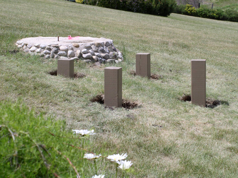


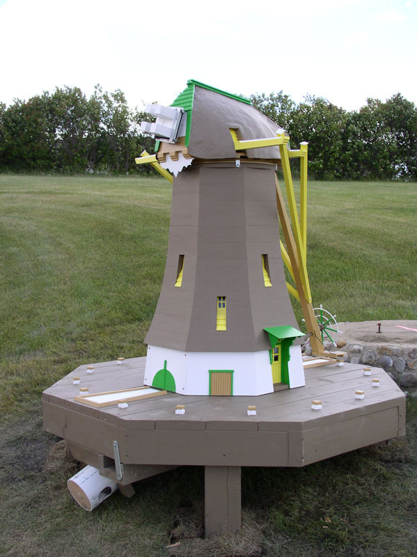

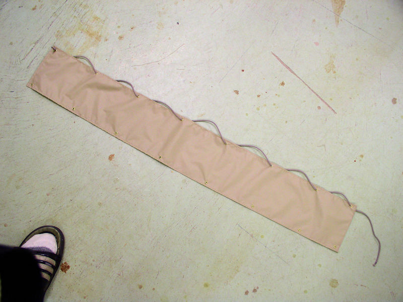
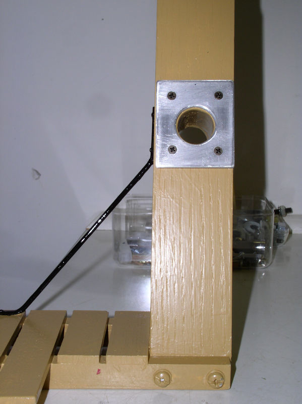

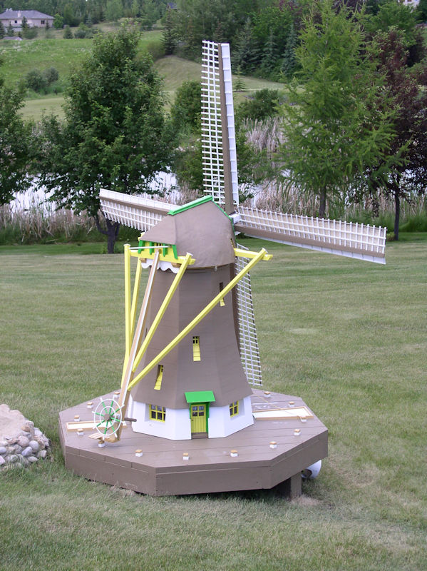

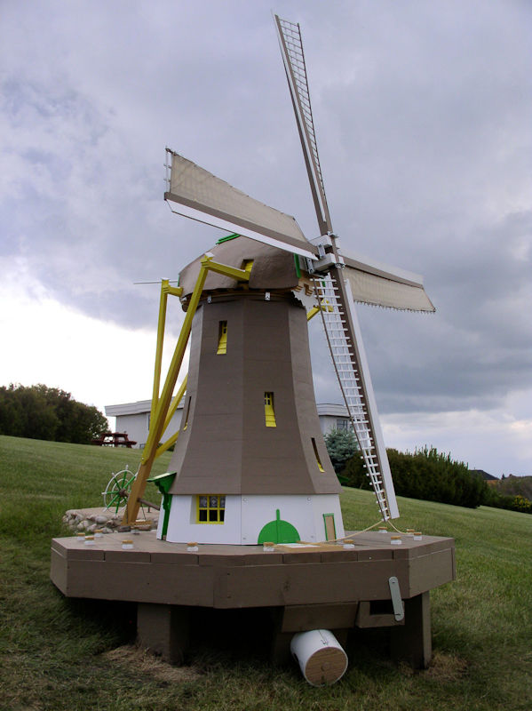


")
")


")


 A -- tooth head
 The involute gear profile is the most commonly used system for gearing today. In an involute gear, the profiles of the teeth are involutes of a circle. The involute of a circle is the spiraling curve traced by the end of an imaginary taut string unwinding itself from that stationary circle called the base circle.
 Where the line of action (N-N) crosses the line (M1-M2) between the two centres (point O) it is called the pitch point of the gears, where there is no sliding contact.
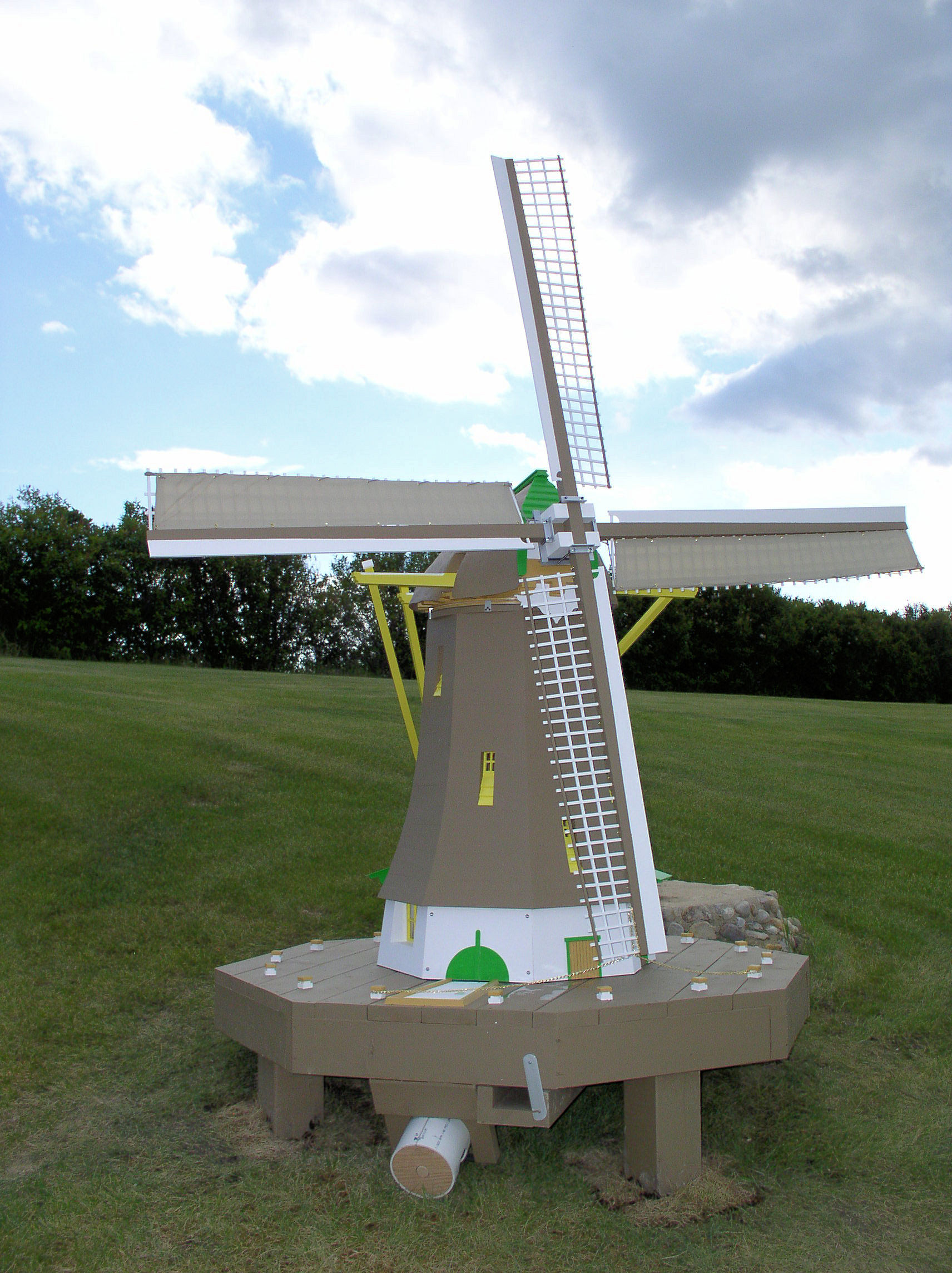
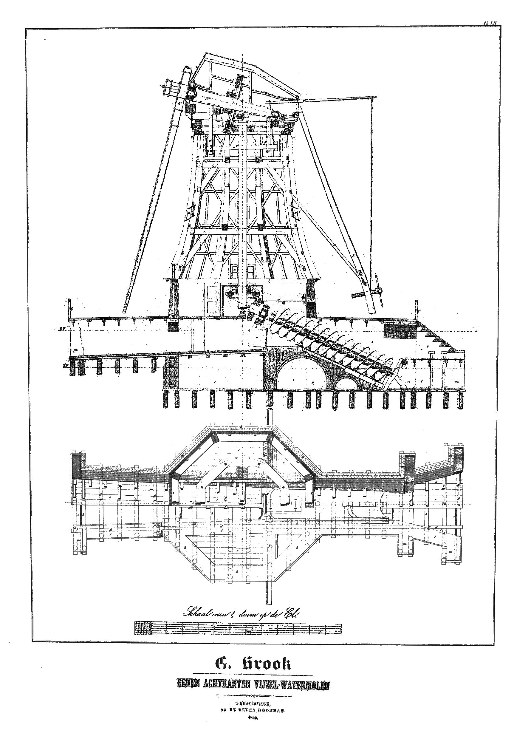