A friend of ours likes apple cider and wanted to make apple cider with his own press. However, an apple cider press was not readily available or expensive. So I offered to make one using left over red oak from my previous projects. Our friend did the research, we agreed on a design, our friend bought the 6-ton hydraulic bottle jack, and the rest was up to me. Various sizes are directly derived from the bottle jack; details are shown in the references section below.
The time reflects construction and finishing time. Design and drawing time is not included.
Pictures
Click on a picture to get a larger picture and then used the back button of the browser to return.
1: 6/4 rough sawn red oak ready to be cut in manageable sizes2: 6/4 rough sawn red oak shortened3: 6/4 rough sawn red oak ripped to width
4: other lumber (leftovers)5: Gluing beams6: Posts and beams squared, trimmed to size, and notches made in posts7: Completed frame8: Outside box of trough; note the filler slats for sloping the inside lining9: Trough lining dry-fitted10: Trough completed11: Cleats under trough12: Detail trough edging13: Funnel14: Trimmed funnel to become the spout15: Hole in front of trough for spout made from a funnel16: Drain parts: slats, slat supports17: Drain: bottom view18: Drain: top view
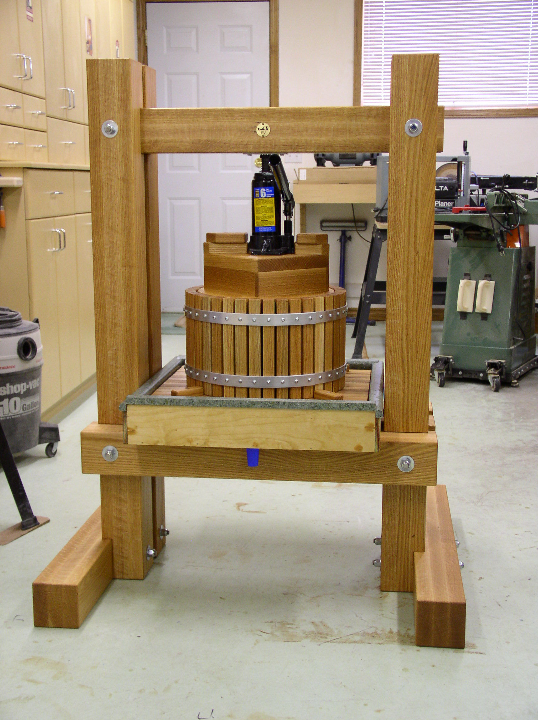
19: Basket parts: slats, hoops, hoop joints20: Hoops screwed to basket slats. Looks like railway tracks doesn't it?21: Basket formed and secured with hoop joints22: Press board and filler top clamped23: Detail finger joint24: Filler piece sides25: Top view filler piece26: Bottom view filler piece27: Bottom view press board assembly28: Top view press board assembly29: Bottle jack ontop of press board assembly30: Press board assembly with handles31: Basket cleats on drain32: Basket on drain33: Construction completed high resolution picture34: Re-assembled after the 100% pure Tung oil application high resolution picture35: Loading the first batch36: The first taste37: Don't let the smile fool you, it is hard at maximum pressure38: Oops, pressure plate failure
How others did it
Aigars Roze made this version of the apple cider press. In my opinion a very well done project with very pleasing result, especially the elegant arch on the top beam. Aigars wrote me that he actually got that idea from a fable!!! And this is what Aigars had to say:
Attached are the final photos of my apple cider press made using your blueprints, but adjusted a bit by available materials and metric system. Ok, this is not made 100% of oak, the trough and press board is made of plywood as it was easier and cheaper to make. I mentioned to you that I was missing some tools therefore I had to involve some friends who helped me. Because of this I got also one disappointment, you can see that on posts right next to trough, and for horizontal legs the holes were made on the wrong side. The whole cider press was treated with linseed oil - 4 times on trough, basket and press board, 2 times on frame. The oil made oak a bit soft therefore some screws went deeper then they should.
I also tried it out and it worked perfectly. The next project is an apple grinder!
Thanks once again for your support during this project.
(Jun-2012) Aigars said that he was "forced" by his wife to entered his apple cider press in a competition organized by a Latvian magazine, "Ievas maja" (Ieva's house). Out of the 200 applications he was one of the 8 winners. When you speak Latvian check out the page with write-up from Ievas maja. Subsequently the magazine asked him to show his apple cider press at the annual Applied Folk Art Fair, the largest in Latvia. The apple cider press is shown here at the fair location.
Congratulations Aigars!
1/4 sheet of 1/2" 5ft x 5ft Baltic birch plywood. Height of sides depend on the counter top material.
1
trough front
21-1/8
3-1/2
7/16
1
trough back
21-1/8
3-1/8
7/16
2
trough sides
22
3
7/16
1
trough lining
3/4
4 feet counter top material
4
trough cleats
5
1
1
glue on underside to keep trough in position on beams
16
drain slats
19-3/4
1
1
red oak; maple is recommended; see also "What went wrong"
4
drain slat supports
19-3/4
1
1
red oak; maple is recommended; see also "What went wrong"
38
basket slats
9
1
1
red oak; maple is recommended; see also "What went wrong"
4
basket cleats
3
1
3/4
red oak to hold basket in place on drain; maple is recommended; see also "What went wrong"
1
round press board
13
1-1/4
red oak; fingerjoint construction
4
filler pieces
8
2-1/4
1
red oak; see construction description
1
filler top
8-1/2
8-1/2
1-1/4
red oak; fingerjoint construction
1
bottle jack back cleat
4
1
1
red oak
1
bottle jack left cleat
4-1/4
1-1/4
1
red oak; length depending on bottle jack base; tapered on one end
1
bottle jack right cleat
3-1/4
1-1/4
1
red oak; length depending on bottle jack base; tapered on one end
1
press board assembly left handle
4-1/4
2-1/4
1
red oak; length depending on bottle jack base; tapered on one end; on top of left bottle jack cleat to enable lifting the press board assembly out of the basket
1
press board assembly right handle
3-1/4
2-1/4
1
red oak; length depending on bottle jack base; tapered on one end; on top of right bottle jack cleat to enable lifting the press board assembly out of the basket
2
basket hoops
47-1/2
1
1/8
aluminium
2
hoop joints
10
1
1/8
aluminium
2
pressure plate
4
1
1/8
aluminum, but stainless steel is recommended; see also "What went wrong"
3
stainless steel theaded rods
36
1/2
(2) 11-1/2" long for top (2) 17-1/2" long for middle (4) 8-1/2" long for bottom
should be safe for food contact; see also "What went wrong"
1
6-ton hydraulic bottle jack
Raw Material
I used as much leftover material from previous projects as possible.
Six boards rough sawn 6/4" red oak. Ranging in width from 8-1/2" to 10-3/4", and ranging in length from 97" to 99". These are used to construct the posts and beams.
The rest of the red oak comes from a pile of trim and cut offs.
4 feet counter top with back splash I bought on sale, and cut up to form the inside lining of the trough.
The hardware I bought, using stainless steel bolts, nuts and screws where possible.
Hand tools -- sanding block, tape measure, square, clamps
Router bits -- 3/16" radius round over bit (Canwood 301-021); finger joint bit (Lee Valley 16J75.01)
Miscellaneous -- 9/16" auger drill bit, pre-drill bits for screws with countersink, 8" dado set
Construction
All measurements are in inches (1 inches = 2.54 cm) because all wood measurements in the shop are in inches. I recommend to cut, shape and sand all pieces and dry-fit them together with clamps.
Terminology & Assumptions
Before we begin it is important that we all speak the same language, so that when I use a term you know what I am talking about.
Posts, Beams
Start off by reducing the rough sawn red oak boards into manageable sizes. Cut three boards in half lengths, and three boards in three equal lengths. Next rip all the cut boards in half. Be careful not to waste any material as you don't have much excess material. The goal is to eventually glue three boards together and then mill it to 4" square. However, if it turns out that the final size is 3-7/8" square then that is fine too as it does not reduce the overall strength of the frame significantly.
Mill one face of each board flat on the jointer. I have typically the jointer set a 1/32" cut. Then run the board through the planer to get the other face flat and parallel to the first one. As soon as a board's second face is flat stop planing that board. Give the planed surface one pass over the jointer to get rid of the snipe of the planer. Then put the board away and continue with the other boards. In the end you have a sequence of long boards for the posts in order of thickness, and the same for the shorter boards for the beams.
For the first post take the thickest board, the thinnest board and a middle board. Do the same for the other posts using the remaining boards. Then follow the same procedure for the beams. For each post and beam arrange the three boards such that the best long edge and short edge are lined up on one side. Keep the nicest board faces on the outside. As the apple cider press is bound to be used outside and exposed to moisture during the pressing process, we use Titebond III glue. Glue the three boards of a post together and clamp them. Remove squeezed out glue with a wet cloth. I let the post cure for 24 hours in the clamps. Do the same for the other posts and beams.
Now we will mill the posts and beams to 4" square. Select a flat face on a post and mark that as the reference surface. On the jointer mill one edge perpendicular to the reference face. On the table saw rip the other two surfaces at 4-1/16" width, and finish those with two passes (1/32" each) over the jointer. My table saw does not cut 4", so I cut 2-1/4", flip over the post or beam and cut the other side. Repeat for the remaining posts and beams. Trim one end of all posts and beams. Again my mitre saw does not have the capacity for a 4" cut, so mark where to cut all the way around the posts and beams. Cut from one side about 3" deep, rotate 180°, line up the blade with the mark, and cut the remaining inch or so. To do this properly it is essential that the blade is square to mitre surface and fence. Next mark the other end and trim off that end in the same way.
Only the posts get notches. All notches are 1" deep, and between 1/32" and 1/16" wider than the beams thickness; ideally a width of between 4-1/32" and 4-1/16". At this point it is prudent to mark on the bottom of the posts which post is which, e.g. LF = left front, RB = right back, etc.. Mark on the post the location of the notches. Install the dado on the table saw at 1" height. Cut the notches using a good mitre fence.
At this point I recommend that you make the trough first (see below), as the outside dimension determine the spacing between the left and right posts plus about 1/8". Mark the location of the threaded rods on the posts and the beams. Again, my drill press has a useable capacity of about 2-1/4", so also here we have to drill one hole from both sides. Work accurately when marking the location, and make sure that the 1/2" auger bit is perpendicular to the drill surface.
With a 3/16" radius round over bit on the router ease over all edges of the posts and beams, except where a beam and post meet. Give everything a final sanding with 220 grid sandpaper.
Cut the required lengths from the threaded rods and ease over the cut edge with a file. Put the frame together.
Trough
The trough consists of a plywood outside box that is lined with countertop material as the trough is the wettest part of the apple cider press when in operation. We aim for an outside trough dimension of 22" square. A 4 feet long countertops is sufficient for this project. The countertop has typically a 3" to 4" back splash and an often nicely rounded over front. The lining for the bottom and front we cut in one piece from the counter top (countertop plus back splash); that is one joint we don't have to worry about. The remaining back splash we use for lining the the back of the trough. The front part of the countertop we use for lining the two sides of the trough.
Calculate the inside dimension of the trough and add 1/4" spare. That is how much we need from the countertop measuring from the back of the back splash. What is left over of the countertop is a strip at the front and that strip we use to line the two side edges. So, make that cut now. Now measure the height of the back splash and the "height" of that front strip put on its edge. From that you have to calculate the best height of the front (where the back splash comes) and the three side for the outside box. The measurements in the material list are for the countertop material I bought.
Now build the outside trough. Cut the pieces from plywood. Glue the front and back pieces to the bottom and keep in place with some brats. Glue the side pieces to the bottom, front and back, and keep in place with some brats. When the glue is dry sand the outside of the trough. Ideally we like the lining (countertop) to slent to the front a bit. So glue a strip of wood or plywood on the bottom at the back. About 1/8" to 3/16" is fine. Glue another strip in the middle of half the thickness.
Fit the countertop inside the trough with the back splash at the front. Once it fit easily you can glue it in place in the trough making sure to apply a generous beat of clear caulking between the lip of the back splash and the top of the front. Use scrap pieces of wood and clamps to ensure that countertop lining stay in place while the glue is drying. Next cut off a piece from the remaining countertop backsplash and fit it at the back of the trough. Glue the back lining against the back making sure to apply a generous beat of clear caulking between the back lining and the bottom lining and between the lip of the back lining and the top of the back. Clamp until the glue is cured. Follow the same procedure for the two sides using the front strip of the countertop. Finally, apply clear caulking to each edge of the trough lining.
Place the trough on the trough beams such that the backside of the trough sticks out 2", and mark the front and back edges of the trough beams on the trough. Make 4 trough cleats of 1" square and 5" long. I waited until I made the drain and basket as there are bound to be cut-offs from that. Glue the trough cleats on the underside of the trough about 1" in from the side and secure each with two 1-1/2" #8 stainless steel flathead screws. Make sure that the trough fits easily over the trough beams with a free play of about 3/16" to 1/8".
Drain, Basket
For the drain and the basket we need 1" square slats. I used leftover material from previous projects for that. Machine those and then trim to required lengths as per the material list. Verify that drain slats and supports fit inside the trough with some free play, 3/16" to 1/8".
Only part of the drain will have drain slats. Mark the location of the holes on the four drain slat supports starting on the back at:
1-1/4
2-5/16
3-3/8
4-7/16
5-1/2
6-9/16
7-5/8
8-11/16
9-3/4
10-13/16
11-7/8
12-15/16
14
15-1/16
16-1/8
17-1/16
Drill the holes through. Next shape the bottom of the drain slat supports to conform to the slope of the trough such that the top of the drain will be parallel to the trough side, i.e. horizontal. The bottom on the back side will be rounded while the bottom on front side will be cut of at an angle to allow for easy flow of juice. Now countersink the holes on the bottom to receive the 1-1/2" #8 stainless steel flathead screws. Ease over all edges with #220 sandpaper.
The drain slat supports are spaced 4" from each other. There will be holes at 2-1/2" and 7-1/2" from the centre to the left and to the right on the bottom of each drain slat. Predrill the holes. Put the fence of the jointer at 85 degrees and set the cutting depth at 1/32". Make two passes with each side of the drain slat such that the bottom is narrower than the top. Ease over all edges.
Line up the drain slats, bottoms up, and put the drain slat supports ontop of those, also bottoms up. Now screw the drain slat supports to the drain slats while making sure that the whole drain is square.
Predrill the basket slats at 1-3/4" from each end to receive the screws from the two hoops. Ease over all edge with #220 sandpaper. The inside top and bottom edge should be rounded over a bit more to make putting in the press board assembly easier.
Cut the two aluminum strips for the hoops at exactly 47-1/2" and remove any burrs. The 38 holes should be 1-1/4" apart starting at 5/8" from the ends. Mark those, predrill with a small diameter bit using cutting fluid!!!!! Then drill to the final diameter while dipping the bit in cutting fluid every so often.
Place the basket slats on a flat surface with the predrilled holes up and place the aluminum strips ontop. Screw the aluminum strips to the basket slats with 3/4" #8 zinc plated round head screws. Next fold this into a round shape. The basket slats prevents you from going too far. The ends might be a bit more difficult. Keep the basket in shape with one or two straps. Take out the 4 screws to the left and the right of the joint of one hoop. Cut two aluminum strips of 10" long for the hoop joint. At first glance the 8 holes in the hoop joint should also be 1-1/4" apart starting again at 5/8" from the ends. However, due to the curve that is not completely true. The four centre holes can be 1-1/4" apart, but the four outside holes have to be slightly further apart like about 1-9/32". I recommend that you measure it. Pre-bend the hoop joints and mount them ontop of the joint. You can squeeze the basket until you have an almost perfect round shape.
Place the trough with drain on the trough beams in the frame. Determine the centre on the top beam, find the corresponding centre on the drain and mark it. Make two marks at 7-1/2" from the centre on the two diagonal lines that connects the corners of the drain. That is where the four basket cleats will come after we have made the press board assembly.
Press Board Assembly
The press board assembly consists of three pieces that are glued and screwed together: the 13" round press board, the 8-1/2" square filler piece, and the 8-1/2" square filler top. The round press board and the filler top requires 1-1/4" finished thickness. For that we mill the two faces of some board on the jointer and planer to a finished thickness of 1-1/4". Next we make the edges perpendicular to a face and parallel to each other. To create enough surface we have to join boards together. I used finger joints for that as those are very strong because of the large glue surface. However, biscuit joints work too, but make sure that the biscuits are well within the finished boards.
To make finger joints it is absolutely essential to use a router table and a fence!!! Setup the finger joint router bit for 1-1/4" thickness, and mount it in the router. Use two 1-1/4" thick cut off pieces of about 10" long. Put the two pieces together and mark the left one "D" and the right one "U". Adjust the position of the finger joint router bit using these two test pieces. Run the piece marked "U" along the router bit with the "U" facing up. Run the piece marked "D" along the router bit with the "D" facing down. Fit the two pieces together with the "U" and "D" facing up. If they are not flush then measure the offset, and raise the router bit half the offset if the "U" test piece is higher, otherwise lower the router bit half the offset. Trim the finger joints from the test pieces and cut the test joint again until perfectly flush.
Use the same procedure of "U" and "D" to do the finger joints of the boards that will make up the round press board and filler top. Clean the finger joints, glue the boards together and clamp them.
While the glue of those boards dry we mill the four filler pieces to the proper size. Next cut a 1" wide and 1/2" deep rabbet at one end of each filler piece. Then glue the four filler pieces into a square (see pictures above) and clamp.
Make the 1-1/4" glued up boards flat with a scrapper and sand them. Use a compass to mark a 13" diameter circle for the round press board. Cut out the press board with the bandsaw staying shy of the line. I then use a disc sander to clean up the edge while each time checking the fit inside the basket. We look for a free play between 1/16" and 1/8".
Cut the filler top at 8-1/2" square. Fit the filler top on the filler square. We need four 2" long #8 flathead screws to secure the filler top to the filler square. With a box corner towards you mark the location of the screw 2" from the front corner into the right side and predrill and countersink. Repeat for the other three sides. Glue the filler top to the filler square and secure with the 2" screws. Once dry run the sides over the jointer taking off not more more than 1/64" with each pass until each side is flush. Use a piece of scrap wood on the back as we will be cutting cross-grain, otherwise tear-out may occur. This will form the filler box.
Place the filler box on top and in the exact centre of the round press board in such a way that one diagonal of the filler box follows the grain direction of the round press board. Trace the outline of the filler box on the press board. Turn the filler box upside down and mark and predrill the screw holes the same as done for the filler top. Also notice that the screws of the filler top will not interfere with those of the press board. Mark the matching screw hole location on the filler piece and drill and countersink. Do not glue together yet!!!
Place the bottle jack on a flat surface. Place a square straight up on the surface against the back of the bottle jack, and measure and write down the distance between the edge of the square and the centre of the bottle jack plunger top. This we call the back offset. Do the same for the left side (i.e. left offset) and the right side (i.e. right offset). Draw two diagonals on the top of the filler box; the intersection is the centre point. Place the filler box with a corner towards you. Mark the back offset from the centre along the diagonal towards the back. Do the same with the left offset along the diagonal towards the left, and the right offset along the diagonal towards the right. These marks are where the three bottle jack cleats should end to hold the bottle jack in place. Cut the bottle jack cleats as per the material list with the length adjusted for your case. Each is held in place with two screw so predrill those holes. Cut the press board assembly handles from the 2-1/4" wide material at the same length as the left and right bottle jack cleats. The handles come on top of the cleats and are held in place with one screw, so predrill those.
Before assembly we like to round over any exposed edges with a 3/16" radius corner round over bit. Put everything loosely together and note where rounding over is appropriate. After the rounding over give everything a final sanding. Glue the press board to the filler box and secure with four screws. Glue the bottle jack cleats to the filler top and secure each cleat with two screws. Glue the handles to the left and right cleats and secure with one screw each.
The last steps
Last, but not least, mount the stainless steel pressure plate with four 3/4" #8 round head screw in the center under the top beam.
Now put everything together. If you have those styrofoam packing noodles then you can fill the basket almost to top with those. Place the press board assembly and the bottle jack on top, and you can then do a dry press exercise.
Finishing
For finishing I used 100% pure Tung oil. The trough, drain, basket and press board assembly gets 5 coats, and the frame gets 3 coats. Allow each coat to dry at least 48 hours; I allow 3 days between coats as red oak has open pores. In order to get good coverage I took everything apart before applying the Tung oil. Let everything dry as long as possible before putting things back together again. Tung oil gives red oak a matt finish that darkens the wood and brings out the wood grain beautifully. Make sure everything is properly sanded otherwise you pay the price as Tung oil brings out all mars, dents and scratches. You may also want to experiment with different wood fillers and a test with an application of Tung oil. My filler darkened far more than the surrounding wood.
In case you like to know
Weight of the cider press frame
70 kg (154 lbs)
Weight of trough, drain, basket
17½ kg (38½ lbs)
Weight of press board assembly, hydraulic bottle jack
8½ kg (19 lbs)
Total weight
96 kg (211½ lbs)
What went wrong
Marked where to drill the 9/16" holes in the beams, drilled the holes from one side to 2-1/4" deep, and put them next to each other on the workbench. It was only then that I noticed that one hole was 1/4" to close to the edge. Was easy to fix by gluing a dowel in the hole, sanding it flat and drilling the hole in the correct position this time.
While predrilling the holes in the aluminum hoops I managed to break 3 drill bits in succession until I realize that working with any metal requires cutting fluid. A tiny drop of cutting fluid goes a long way.
The 100% pure Tung Oil was chosen because of its food safety, both wet and dry. However, red oak is a very porous wood which causes the drying time to be very long indeed. Take two pieces of red oak apply 100% pure Tung Oil, let it dry for 3 days (23°C and 30% humidity), put the two pieces against each other and within a minute the touching surfaces are wet again. Put your warm hand ontop of a "dry" surface and within seconds that surface is wet again. Unless you have all the time in the world, I recommend not to use %100 pure Tung Oil like I did. I believe that a better choice is Polymerized Tung Oil -- safe for food contact once dry --, or any of the Tried & True (TM) Traditional Finishes -- non-toxic and safe for food contact.
When the press was taken into production and the pressure from the bottle jack was increased some cracking noise was heard as if wood was breaking, but initially we did not see anything wrong. Later on we noticed that the two aluminum pressure plates under the top beam were pushed into the wood by the plunger of the bottle jack. Clearly a stainless steel plate is needed here. An e-mail from Julian Hale summarized it nicely, and I quote: "The press looks fantastic. One thing that seems to be missing from the "What went wrong" section is that your friend forgot to grind the apples before pressing them. A stainless pressure plate may be a good idea anyway, but the strain on the wood and overall difficulty in extracting the cider would be greatly reduced (if not eliminated) if the apples were prepped first. A wide-mouth (new) garbage disposal mounted in a simple stand would make short work. I positively cringed when I saw that whole apples were being loaded into the barrel. The horror! Great craftsmanship, though. A lesser press would not have survived that." Thanks Julian for this constructive feedback.
Half way through pressing the first batch of apples we noticed drops of apple cider appearing at the end of several of the basket slats. The porosity of red oak made it not a suitable material. Recommend a more dense wood, like maple, for the basket and drain.
The relative short handle of the hydraulic bottle jack made it hard, even for an man, to apply maximum pressure. A longer handle is recommended.
References
Our design was based on the one published by Ready Made (web site no longer available, but instead of using "cheeses" we use the basket method published by Mother Earth News. We did not copy the designs as is, but modified it based on the 6-ton hydraulic bottle jack we bought. Assumptions are highlighted.
NOTE 1: For normal operation the screw of the bottle jack is half extended (1½"). This is taken into account in determining the space between top beam and trough beams.
NOTE 2: The screw of the bottle jack can be fully extended, i.e. an additional 1½", to give that extra squeeze if needed. This is taken into account in determining the height of the filler piece so that the pump handle of the bottle jack does not hit the top of the basket.


