From a very young age I was fascinated with clocks, especially the big ones with those heavy weights and the moving parts. Their slow ticking had a calming effect while I was reading or just doing nothing. In those days I did not have a wristwatch or alarm clock. Only the man of the house had a pocket watch that was frequently compared with the time given by the main clock in the living room or hallway. And then there was the alarm clock next to the bed of mom and dad. When I woke up in the middle of the night and I wanted to know what time it was, the only solution was to stay awake and listen to the chiming of the main clock sometime, somewhere in the house.
Making my own grandfather clock has been on my to-do list for a long time. A close friend in South Africa had built one too. My mind was made up when I saw that one; and that was in 1989. In October 2008 I started seriously thinking about the project and doing some more research, which lasted some three months. The results of that can be found in the references section below. My clock case looks very similar to the Winchester Grandfather Clock of Oakside Classic Clocks which is not surprising because I like that style (pictures up to 04). My design and drawings took about three months and were done based on the various dimensions of the Kieninger HTU movement. Comparison between my clock case and the Winchester:
This (my) clock case
Winchester case
height x width x depth
83¾" x 24¾" x 14¼"
80" x 21" x 13¼"
hood style
Slides off to the front to provide access to the movement.
Is a fixed extension of waist and has rear access for movement removal.
back style
Flat back intended for placing against a wall.
Mouldings and columns (spindles) go all around the back allowing this case to be used free standing as well.
opening mechanism
¼" rare-earth magnets and knobs
Lock and key with escutcheon
movement cost
US$2,950, that is Can$4,253 including duty and delivery (Jan-2009) Movement is now US$2,090 (Nov-2009)!!!
£1,923 (USA & Canada, Nov-2009)
case cost
wood Can$349 glass & hardware Can$342
total cost
Can$4,944 + 205¼ hours labour
£5,481 or €5,620 (USA & Canada, Nov-2009)
The time reflects construction and finishing time, and also includes some 8-1/2 hours of lost time due to mistakes made during the construction. Design and drawing time is not included.
---=== NOTICE ===--- The 3-dimensional drawings 13 to 26 still have to undergo the final review. ---=== NOTICE ===---
Pictures
Click on a picture to get a larger picture and then used the back button of the browser to return.
Winchester grandfather clock (courtesy Oakside Classic Clocks) This is my inspiration!Kieninger HTU movement and dial (courtesy Klockit) This is what I bought!1: Movement arrived in 4 boxes: movement, pendulum, chime tubes, weights2: Content of movement box: the movement itself, dial with moon phase, weight shells, hands, other hardware, documentation3: Content of chime tubes box4: Content of pendulum box5: Rough sawn lumber6: Temporary movement stand7: Movement mounted8: Cut up lumber9: Flatten, straighten, planed to ¾", ripped to size10: Leftovers from ripping; enough for cleats and hood roof11: Hood top front stretcher12: ¾" stock trimmed and sorted13: Mortises & tenons14: Mortises & tenons dry-fitted15: Patching wrong dado cut16: Finished dado cuts17: Arch drawing jig18: Arch drawing jig19: Hood and waist pieces for frame edging20: Base pieces laid out21: Frame edge detail22: Disaster struck! Bye-bye hood door top stretcher22a: Routing inside arch with sacrifice board23: Hood pieces dry-fitted24: Waist pieces dry-fitted25: Base pieces dry-fitted26: Base frames glued27: Base frames waiting for glue to cure28: Frame edge removed between top and middle stretchers of waist side frame; removed back edge above middle stretcher29: Waist frames waiting for glue to cure30: Hood frames waiting for glue to cure31: Movement seat board32: Inside edge of frame edge removed; corners still need to be cleaned up33: Detail of holes for knob and magnets34: Setup for door hinge recess35: Routing hinge recess in hatch panel36: Start position, left recess and left router bit lined up37: End position, right recess and right router bit lined up38: Hinge recess in door39: Routing hinge recess in base front panel40: Hinge recess in front panel41: Hatch panel open42: Hatch panel closed43: Base section (upside down) glued using a temporary back board44: Base bottom board45: Base section without bottom board46: Leveller detail; note that it is mounted against the cleats47: Base with bottom board, but without compartment board48: Waist section glued using 3 temporary back boards49: Waist section50: Base with waist bottom support cleats dry-fitted51: Waist dry-fitted on base52: Base with base boards and waist bottom support cleats installed53: Waist glued to base54: Hood holding cleats glued to waist55: Base/waist completed except for base compartment board and back board56: Hood section glued using a temporary back board57: Hood section58: Dial trim panel parts59: Dial trim panel details; smallest tenon/mortise I ever made with the Leigh FMT (3/8" x 7/8" x 1/8")60: Dial trim panel glued61: Dial trim panel glued into hood62: Hood with dial trim panel63: Hood temporary placed64: Moulding material65: Shaping the double moulding66: Shaping the double moulding (note the marked high spot)67: Wood chips from milling the moulding68: Moulding shaped69: Front moulding installed on hood70: Hood with moulding on top of waist71: Installing base/waist moulding72: Base/waist moulding installed73: Everything put together74: Cutting waist edge on back board75: Base compartment board installed76: Rear view of hood77: Rear hood detail78: Back board79: Back board installed80: Movement installed81: Movement side view82: Hood in place83: Full view84: Front view hood with 10 roof slats85: Remaining roof slats and filler piece86: Back view hood with all roof slats87: Jointing angle on roof slat filler88: Roof slat filler and side piece glued89: Scrape and sand roof inside and outside90: Setup router for frieze and top moulding91: Setup frieze for routing92: Ready for routing 1/2" edge on frieze93: Front frieze with 1/2" gouge for little arch94: Front frieze ready for tracing roof line on back95: Side frieze glued in place96: Frieze installed97: Same setup for routing hood arched top moulding98: Hood arched top moulding routed, but not yet trimmed99: Side moulding glued and clamped100: Front left/right moulding glued in place and kept straight with a slat101: Top moulding trimmed at 63.5° to fit other mouldings102: Outside arch of top moulding shaped103: Hood trim glued in place104: Hood finished, except the columns105: Hood backside; note the photo frame turners106: Complete clock so far107: Rough pieces to make the columns108: L-shape front column glued109: Two back column halves110: Paper glued on temporary pieces111: Column blanks glued112: Column blanks trimmed to length; note the paper joints113: Corners taken off from the column blanks114: Capital of test column115: Columns with template116: Columns with template117: Flute jig, back and top glued, sides marked118: Sides glued119: Flute jig ready120: Column mounted in jig121: Flute routed122: Back column halves split123: Back and front columns124: Columns glued and clamped125: Hood finished126: Construction completed127: Hood stained128: Base/waist stained129: Compartment board, base hatch door, movement seat board, hood door, waist door stained130: Felt pad on top of left hood holding cleat131: Felt pad against top of left hood holding groove132: Back side view high resolution133: Front view, no hood high resolution134: Front view, no doors high resolution135: Hood detail high resolution136: Waist detail high resolution137: Base detail high resolution138: Hood side view high resolution139: Waist side view high resolution140: Hinge detail high resolution141: Full view high resolution142: Full view high resolution143: Full view, open doors high resolution144: Full view high resolution145: Base hatch door high resolution
How others did it
Dominic Brindisi got hold of my drawings when I had barely started my own construction. He had laid his hands on an old Hermle 1161-853/114cm movement, and he was eager to get started on the case. That certainly kept me on my toes to stay ahead and to keep the drawings up-to-date with the latest changes. We exchanged many emails discussing issues.
Dominic had some limitations with respect to available woodworking machines, but he came up with good ideas to deal with that. Notice that he did not use glass in the waist sides, no arches at the top of the waist door and base hatch, and in order to ensure good sound he did the hood sides with scroll saw work that is covered on the inside with black speaker cloth. He used MinWax Special Walnut stain and finished the case with hand rubbed boiled linseed oil. And last, but not least, at a total cost of US$ 550.00 he certainly did it cheaper than me. The Hermle movement uses chime rods that are mounted on a block that is visible in the back of the hood.
In his own words, "I cleaned and oiled the movement and checked for excessive bushing wear and all was within acceptable standards. The movement is operating flawlessly and keeping accurate time, it took a lot of tweaking to get everything in sync. I learned a lot about grandfather clocks and I have the leveling procedure down pat now. I used the level just to get it in the ballpark and then used my ear to finish leveling and get the clock in beat, works fine. The clock is quiet and the chimes are not that loud at all."
Dominic, I enjoyed following your project and the picture shows what a fine grandfather clock it has become. Thanks for allowing me to share that with others.
Chris Redfearn from Halifax in the north of England sent me the following email.
I came across your site via Oakside Classic Clocks whilst researching where to buy a mechanism. I have harboured a desire to build a grandfather for more than 30 years but children, work and barn renovations have got in the way till this year. I was very impressed with the comprehensive detail you put on the site which enabled me to build the clock with relative ease. There are a few small differences but these are not substantial e.g my hood roof is made from several sheets of kerf-cut cherry-faced MDF laminated into the required curve. As you can see from the pictures I used cherry which I have not worked with before, but the result is pleasing and the clock is a great addition to our house. I know from talking to Frank at Oakside (where I bought the mechanism) that he wished me to send you some pictures of the finished clock and I had in any case intended to do so because your site is a great resource.
In my reply to Chris I said, "Your grandfather clock looks great and looks like a carbon copy of mine, which is of course not surprising as you used my drawings. I have never used cherry, but your clock has a nice warm look." Chris also allowed me to publish pictures of his perfect looking grandfather clock. Thanks Chris.
François Swanepoel is an enthusiastic home woodworker from South Africa. He also built his own CNC MechMate, or Computer Numerical Control router system. Someone contacted François if he could cut certain grandfather clock parts on his CNC MechMate. François wrote, "After seeing the plans it sparked a life time dream to build a grandfather clock for myself."
Here are the pictures of his version of the grandfather clock. A verry nice job indeed.
James P. Davenport sent me his first email on 9-Nov-2020. On 18-Jan-2021 he sent me his last email with pictures of his finished product. This is what he had to say:
I thought you might be interested in my rendition of your fabulous clock case. Your plans are extraordinary in their detail, making the project relatively straightforward for an experienced woodworker. There were several steps that I think I improved on, such as fitting the roof boards without gaps (a mathematical matter of working out the proper shape of the individual boards) and creating the columns without glue-ups (full round columns can easily be split or three-quartered on the table saw using a proper jig). But for the most part, your plans anticipated every necessary step.
My version is made of American cherry, finished with a water-based stain and multiple coats of shellac, rubbed out and waxed. I purchased my clock movement from your friend Frank Redmile (i.e. Oakside Classic Clocks), and he has been very helpful on this aspect.
Thanks again for publishing your plans on the web. I very much enjoyed this project.
My reply was, you are obviously an experienced woodworker, and your version of the grandfather clock made out of cherry is beautiful.
During that period we had a few other email exchanges. Among others, Jim suggested that I numbered the cut list. My comment was that in hindsight numbering the cut list items is a good suggestion. However, adding numbers to the drawings make them even more crowded then they are already. Secondly, I am 77 years and spend my time on other things.
Cris Donohue sent me his first email on 25-Jan-2021. On 24-Jul-2021 he sent me his last email with pictures of his finished product. This is what he had to say:
My grandfather clock is now indoors and working. I have attached a few photos of how it has turned out as you have asked. The front door isn't hung as I have recently lost the use of my left hand and this may well be my last woodworking project for a while.
I have had to make a few changes as my workshop isn't well populated with tools and I've had to use timber of commercially available thicknesses, which was a challenge at times. My movement is cable driven with gong rods, so have made a sounding box on the rear of the back plate. The other major difference is that my columns are simpler as I wanted to try hand carving for these.
The timber is an Australian native hardwood, locally called Tasmanian Oak, which despite its name is not an oak but is a Eucalypt and can come from any one of three varieties of tree. I have sourced all the same timber based on colour and grain (although very similar, there are some subtle differences between the 3 varieties) and have used Alpine Ash which again confusingly, is not an Ash but is Eucalyptus Delegatensis. I have finished the timber with a walnut stain.
I am very happy with the way it has turned out, and I would like to thank you again for your highly detailed plans. I have no doubt that my clock would not be as pleasing for me were it not for the details you provided.
My reply was, thank you for sending me some pictures. Looking good.
For construction the pdf format drawings 04 to 10 contain all the required details. Recommend to print the double scaled pdf drawings 04, 05 and 06, as those will show the details better. With letter size (8-1/2" x 11") printing using the Adobe Reader use "Page Scaling" set at "None" for smallest 1/2" margin.
Please note that the 3-dimensional drawings 11 to 26 may not show all the details; they are only intended to show relationship between individual pieces.
Drawing 01 - An approximate 3D drawing of the movement so that it can be put in the 3D drawing of the case to see if everything fit together properly.
Drawing 02 - Front and side view of movement with dimensions.
A = hand shaft center to pendulum bob adjust screw
B = minimum inside case width = diameter pendulum bob + 6" to 8" to allow automatic beat adjustment; normal pendulum swing is 14"
C = hand shaft center to weight drop at end of 8th day
D = hand shaft center to top chime tube mount (see 1)
E = tip hand shaft to back mounted chime tubes (total depth of movement)
F = overall width chime tube mount frame (total width of movement see 2)
G = hand shaft center to bottom of movement (begin movement seat board)
H = front movement plate to front surface of dial
I = front surface dial to front of weight assemblies
(1) = inside clock case length is weight drop (C) plus the greater of top chime tube mount (D) and top edge of dial (hence total height of movement)
(2) = overall width is determined by the greater of width chime tube mount frame (F) and minimum inside case width (B)
(3) = center point of moon dial is 5-9/16" above the hand shaft center; see references below
Drawing 04a - Case front view
Drawing 04b - Case front view
Drawing 04 - Case front view One drawing in double scale on 4 sheets of letter size paper that need to be glued together.
Drawing 08b - Case top sections C-C (hood), D-D (waist)
Drawing 08c - Case top sections E-E (base)
Drawing 09 - Movement seat board
Drawing 10 - Column details
Drawing 11 - Full case view
Drawing 12 - Full case view with doors open
Drawing 13 - Full case view
Drawing 14 - Case main components
Drawing 20 - Hood construction
Drawing 21 - Hood construction (revision: 23-May-2014)
Drawing 22 - Waist construction
Drawing 23 - Waist construction
Drawing 24 - Base construction
Drawing 25 - Base construction
Drawing 26 - Back board construction
Materials List (inches)
Here is the detail materials list. All wood is solid red oak unless stated otherwise. Measurements up to 1/16th are accurate. Measurements of 1/32nd and 1/64th only indicate the theoretical measurements and we recommend that you cut those items a little bit oversized and trim accordingly.
no.
description
length
width
thickness
suggested basic material, comments
Hood
2
front stile
21-33/64
2-7/16
3/4
cut at length=22" shape top to fit roof mortised to receive front stretchers rabbet W=3/4" D=1/2" on outer edge to received side stile
1
front stretcher, top
16-1/8
8-11/16
3/4
14-5/8" with tenon (2) L=3/4" W=1-1/2" T=3/8" C=2" o.c. both ends arch radius I=6-3/8" O=10-7/16"
1
front stretcher, bottom
16-1/8
1-3/16
3/4
14-5/8" with tenon L=3/4" W=1" T=3/8" o.c.both ends
2
side stile, front
20-3/8
2
3/4
inside edge shaped with 3/8" frame bit
2
side stile, back
20-3/8
2-1/4
3/4
inside edge shaped with 3/8" frame bit rabbet W=3/8" D=1/2" on back edge to received back board mortised to receive roof top back stretcher
2
side stretcher, top
7-7/8
5-1/2
3/4
inside edge shaped with 3/8" frame bit ends shaped with 3/8" reversed frame bit
2
side stretcher, bottom
7-7/8
2-1/4
3/4
inside edge shaped with 3/8" frame bit ends shaped with 3/8" reversed frame bit
2
3/4-column, front
17-1/8
2 Ø
turned with appropiate base/capital and flutes
2
1/2-column, back
17-1/8
2 Ø
turned with appropriate base/capital and flutes
1
front frieze
21
7-5/8
3/4
arch radius I=7-11/16" O=11-3/16" inside arch decorated with R=1/2" core box bit
2
side frieze
12-3/8
3-1/2
3/4
2
front trim
4
1-1/4
1/2
2
side trim
12-7/8
1-1/4
1/2
1
back stretcher, top
19
5-5/8
3/4
18" with tenon L=1/2" W=1" T=3/8" o.c. both ends arch radius I=8-15/16" O=10-7/16"
2
roof slat, left/right
11-5/8
1-1/2
3/4
cut at length=12" width=1-3/4" shaped to fit roof line
2
roof slat, filler left/right
11-5/8
1-3/16
3/4
cut at length=12" width=1-1/2" shaped to fit roof line
18
roof slat
11-5/8
1
3/4
cut at length=12" shaped to fit roof line
1
dial trim panel (or use next 3 items as alternative)
20-3/4
16-1/8
1/4
red oak plywood; 2-3/4" wide border arch radius I=4-3/8" O=7-1/8" The hoot front frame overlaps the dial trim panel by 3/4" all around.
2
dial trim panel, stile
18-3/8
2-3/4
1/4
red oak; cut at length=19" mortised to receive stretchers
1
dial trim panel, top stretcher
11-3/8
7-3/8
1/4
red oak; 10-5/8" with tenon (2) L=3/8" W=7/8" T=1/8" C=1-3/8" o.c. both ends and spread over the bottom 2-3/4" arch radius I=4-3/8" O=7-1/8"
1
dial trim panel, bottom stretcher
11-3/8
2-3/4
1/4
red oak; 10-5/8" with tenon (2) L=3/8" W=7/8" T=1/8" C=1-3/8" o.c. both ends
1
top moulding, front top arch
17-23/64
5-7/8
1-7/8
arch radius I=9-7/16" O=11-3/16"; see drawing 07 for profile
2
top moulding, front left/right
4-37/64
1-7/8
1-3/4
joins arch at 63.4° angle; see drawing 07 for profile
2
top moulding, side
14-1/4
1-7/8
1-3/4
see drawing 07 for profile
1
hood/waist moulding, front
21-3/4
1-7/8
1-3/4
moulding is attached to hood and has a 1/2" deep and 9/16" wide groove; see drawing 07 for profile
2
hood/waist moulding, side
12-3/4
1-7/8
1-3/4
moulding is attached to hood and has a 1/2" deep and 9/16" wide groove; see drawing 07 for profile
2
door stile
17-11/64
2-1/4
3/4
cut at length=18" inside edge shaped with 3/8" frame bit
1
door stretcher, top
11-1/2
6-7/8
3/4
arch radius I=4-7/16" O=6-11/16" inside edge shaped with 3/8" frame bit ends shaped with 3/8" reversed frame bit
1
door stretcher, bottom
11-1/2
2-1/4
3/4
inside edge shaped with 3/8" frame bit ends shaped with 3/8" reversed frame bit
Waist
2
front stile
46-1/2
1-5/8
3/4
mortised to receive front stretchers rabbet W=3/4" D=1/2" on outer edge to received side stile
2
front stretcher
16-1/8
3
3/4
14-5/8" with tenon L=3/4" W=2" T=3/8" o.c. both ends
2
side stile, front
51-3/8
2
3/4
inside edge shaped with 3/8" frame bit
2
side stile, back
51-3/8
2-1/4
3/4
inside edge shaped with 3/8" frame bit rabbet W=3/8" D=1/2" on back edge to received back board
2
side stretcher, top
7-1/16
2
3/4
ends shaped with 3/8" reversed frame bit
4
side stretcher, middle & bottom
7-1/16
4
3/4
inside edge shaped with 3/8" frame bit ends shaped with 3/8" reversed frame bit
1
movement seat board
17-7/8
4-1/2
3/4
shaped as per drawing 09
2
cleat under movement seat board
10-1/16
1-1/4
3/4
1
hood holding cleat, front
18-7/8
1/2
1/2
cleat is attached to waist; see drawing 07 for profile
2
hood holding cleat, side
11-5/16
1/2
1/2
cleat is attached to waist; see drawing 07 for profile
2
door stile
41-1/8
2-1/4
3/4
inside edge shaped with 3/8" frame bit
1
door stretcher, top
11-1/2
3
3/4
inside edge shaped with 3/8" frame bit ends shaped with 3/8" reversed frame bit arch radius I=14-5/8"
1
door stretcher, bottom
11-1/2
2-1/4
3/4
inside edge shaped with 3/8" frame bit ends shaped with 3/8" reversed frame bit
1
back board
83
20-1/8
1/2
red oak plywood; extends over full length of case
1
bottom support cleat, front
19-3/8
1-1/2
3/4
glued with biscuits to waist bottom
2
bottom support cleat, side
9-9/16
1-1/2
3/4
glued with biscuits to waist bottom
Base
2
front stile
12
1-5/8
3/4
mortised to receive front stretchers rabbet W=3/4" D=1/2" on outer edge to received side stile
1
front stretcher, top
19-1/8
2-1/8
3/4
17-5/8" with tenon L=3/4" W=1-1/2" T=3/8" o.c. on both ends arch radius I=44-11/16"
1
front stretcher, bottom
19-1/8
5-1/4
3/4
17-5/8" with tenon (2) L=3/4" W=1-1/2" T=3/8" C=2-3/4" o.c. both ends
2
side stile, front
12
2
3/4
inside edge shaped with 3/8" frame bit
2
side stile, back
12
2-1/4
3/4
inside edge shaped with 3/8" frame bit rabbet W=3/8" D=1/2" on back edge to received back board
2
side stretcher, top
8-9/16
2-1/4
3/4
inside edge shaped with 3/8" frame bit ends shaped with 3/8" reversed frame bit
2
side stretcher, bottom
8-9/16
6-1/4
3/4
inside edge shaped with 3/8" frame bit ends shaped with 3/8" reversed frame bit
2
side panel
8-1/2
4-3/16
3/8
1
cleat under waist bottom support cleat, front
17-3/8
1
3/4
glued and screwed to inside of base front front edge shaped following top front stretcher
2
cleat under waist bottom support cleat, side
11-1/16
1
3/4
glued and screwed to inside of base side
1
bottom board
19-3/8
11-1/16
3/4
red oak plywood
1
cleat under bottom board, front
18-5/8
1
3/8
glued and screwed to inside of base front
2
cleat under bottom board, side
11-1/16
1
3/8
glued and screwed to inside of base side
1
compartment board
15-3/8
8-1/2
1/2
red oak plywood
1
waist/bottom moulding, front
21-5/8
1-7/8
1-3/4
see drawing 07 for profile
2
waist/bottom moulding, side
12-11/16
1-7/8
1-3/4
see drawing 07 for profile
1
baseboard, front
22-3/8
4
3/4
top angled at 45°
2
baseboard, side
13-1/16
4
3/4
top angled at 45°
2
hatch door stile
5-39/64
2-1/4
3/4
cut at length=6" inside edge shaped with 3/8" frame bit
1
hatch door stretcher, top
14-1/2
2-7/8
3/4
inside edge shaped with 3/8" frame bit ends shaped with 3/8" reversed frame bit arch radius I=42-3/4" O=45"
1
hatch door stretcher, bottom
14-1/2
2-1/4
3/4
inside edge shaped with 3/8" frame bit ends shaped with 3/8" reversed frame bit
1
hatch door panel
14-7/16
2-5/16
3/8
arch radius I=43-1/16"
Hardware
1
Kieninger HTU movement
68-3/8
14-1/8
9-1/2
cable, 9-tube, dial with moon phase, pendulum; from KlockIt
4
2" swivel leveller
2
1-1/2
Lee Valley 01S06.02
4
corner brackets
3
3
13/16
Lee Valley 01S04.01 (sold in set of 4)
4
1/4" rare-earth magnet set
3/8 Ø
Lee Valley 99K33.10 (sold in set of 4)
3
1"x1" solid brass knob
1
1
Lee Valley 00W90.10
6
2-3/4" x 5/16" finial lift-off case hinges
5
5/16
5/16
Lee Valley 01D02.70 (sold in set of 2)
9
photo frame turners
1
3/8
Lee Valley 00F1150 (sold in package of 8) to hold hood to back board
Lee Valley 01Z12.81 (sold in pkg of 100) for attaching back board (23), cleats under movement seat board (4), hood holding cleats (7), waist bottom support cleats (4), cleats under waist (6), base compartment board (3)
16
pan-head #8 Phillips ½"
1/2
#8
for attaching levellers
4
flat-head #8 Phillips 1½"
1-1/2
#8
for attaching movement seat board
12
biscuit #20
for attaching hood to hood/waist moulding, and attaching waist to bottom support
1
glass, hood door
16
11-3/8
3 mm (~1/8")
shaped to match door frame; arch radius=4-3/4" edge height=11-3/8"
2
glass, hood side
13-1/4
7-3/4
5 mm (~3/16")
approx. 1-1/8" bevel all around
1
glass, waist door
37-1/4
11-3/8
3 mm (~1/8")
shaped to match door frame; arch radius=14-15/16" edge height=36-1/2"
2
glass, waist side
39-1/8
6-15/16
5 mm (~3/16")
approx. 1-1/8" bevel all around
1
woodfiller
e.g. Woodwise Red Oak Woodfiller
1
wood glue
e.g. LePage carpenter's glue (or Titebond III wood glue)
1
stain
e.g. Cloverdale Timberlox Wiping Stain 16204 Clear Base
1
varnish
e.g. Cloverdale Timberlox Acrylic Urethane Varnish 42314 Clear Satin Finish
1
sealant (caulking)
e.g. G.E. Clear Window & Door (Silicone) Sealant
4
felt pad
3/4
7/16
1/32
use 3/4"x3/4" pads and trim to size
Material List Legend
For example:
18-1/8" with tenon (2) L=3/4" W=1-1/2" T=3/8" C=2-3/4" o.c. both ends = 18-1/8" long with 2 tenons on both ends. Tenons are 3/4" long and hence overall length is 19-5/8" (18-1/8 + 3/4 + 3/4). Tenons are 1-1/2" wide and 3/8" thick. The centre of the tenons are 2-3/4" apart, and place on centre (o.c.) of the end.
arch radius I=4-7/16" O=6-11/16" = The radius of the inside arch is 4-7/16" and the radius of the outside arch is O=6-11/16".
Raw Material
For my projects I prefer rough sawn red oak. In this case I got a cheap deal on 4/4" dressed red oak which is actually 15/16". I needed 50 bdft and bought 57 bdft. I also need 6 bdft of 8/4" dressed red oak for the mouldings and bought 9 bdft. Where possible I used leftovers from previous projects.
Required Tools
Power tools - table saw, miter saw, band saw, planer, jointer, router and table, drill press, biscuit jointer, random orbit sander, wood lathe (17-1/8" between centres)
Jigs - Leigh Frame Mortise and Tenon (FMT) jig, 3/8" spiral upcut router bit (Leigh 173-500C); for dial trim panel only: 1/8" spiral upcut bit (Leigh 164C) for mortise and 3/8" spiral upcut bit (Leigh 173-500C) for tenon
Router bits - 3/8" reversible ogee frame bit (Lee Valley 16J67.51), 3/8" rabbeting bit (Lee Valley 16J32.70), 31/64" plywood bit (Lee Valley 16J04.81), 3/8" laminate flush trimming bit (Lee Valley 16J09.06), 45° chamfer bit (Ditmar 102R4-45), 1" core box bit (Lee Valley 16J15.58), 3/8" core box bit (Lee Valley 16J15.03)
Miscellaneous - pre-drill bits for screws with countersink, 1-1/4" hole saw, 8" dado set, sand paper #220 and #320, 3/4" and 1-1/2" sanding drums
Construction
All measurements are in inches (1 inches = 2.54 cm) because all wood measurements in the shop are in inches. I recommend to cut, shape and sand all pieces and dry-fit them together with clamps.
It is assumed that you are familiar with all your machines and Leigh jigs. Check out the Workworking Tips section for basic machining tips of rough sawn wood.
November 2nd, 2009, was the first day that saw dust was made for this project. The rough sawn red oak lumber has been in the workshop for almost 3 months, properly stacked with thin slats between each board to let them adjust to the temperature and humidity of the workshop. The lumber was checked for staples so that no sharp blades would be ruined! A list was made of the measured lumber for later use. Spots were marked that cannot be used.
To give an idea of the required construction and finishing time:
Activity
hours
Test stand, test movement seat board, movement installation
5¾
Cut up rough-sawn boards
3½
Straighten boards and plane to 3/4" thick
6¾
Rip to width, cut to length
14¾
Mortises & tenons of front frames, rabbets of front frames and back stiles
Movement seat board, plane 1/2", 3/8" and 1/4" boards, dial trim panel, base panels
9½
Knobs, magnets, hinges
8¼
Sanding
3¼
Base assembly
10¾
Waist assembly
7
Hood assembly
2¾
Mouldings
11¾
Back board, base compartment board
5½
Moment of truth
3
Hood roof, frieze and moulding
22¼
Hood columns
23¼
Stain, varnish
12¾
Install hardware & glass, place clock case, install movement
8½
GRAND TOTAL
205¼
On March 14th, 2010, the grandfather clock was installed in our dining room and fully operational.
Terminology & Assumptions
Before we begin it is important that we all speak the same language, so that when I use a term you know what I am talking about.
Hood - top part of the clock case that houses the actual clock movement with an access door to the dial and hands. The hood is removable to provide access to the movement and tubes.
Waist - the narrower middle part of the clock case that houses the pendulum and weights with an access door to get to those.
Base (or bottom) - the lowest part of the clock case. The base contains the levellers to adjust the clock case so that it is absolutely vertical, and more importantly to ensure that the movement seat board is absolutely level. The base has a small compartment immediately behind the hatch panel (flip-down door) to keep the clock documentation and the winding crank. Upon completion the waist and base form one piece.
Stile - vertical piece of wood.
Stretcher or rail - horizontal piece of wood, often mounted in between two stiles.
Slat - a long narrow strip of wood such as the roof slats of the hood.
Cleat - usually a bit bigger than a slat and used to strengthen the construction.
Frieze - a decorative piece of wood like at the top of the hood.
Moulding - a decorative piece of wood as used at the top of the hood, and as a separator between hood and waist, and between waist and base.
General comments on drawings and construction
Drawings - The most important drawings are the double size drawings 04, 05 and 06, which are the front and side views and cross sections. Drawings 07, 09 and 10 are the back board, movement seat board and column details. All these drawing you should have pinned up on the wall in your shop for easy reference.
Measurements - I like to standardize the measurements in 1/8" and if absolutely necessary 1/16". The radius of the moon dial is 4-9/16" and hence the derived hood door arches end up being multiples of 1/16". As there is a gap of 1/16" between the inside of the hood and the outside of the waist that means that waist depth measurement are multiples of 1/16" too.
Arches - You will notice that I use a "single" piece of wood to make each arch. For that we need well seasoned quarter sawn wood that has been in the workshop environment for many months. Although constructing the arches from 2, 3 or even 4 segments of wood glued together are more stable, in my opinion an arch from a single piece of wood with the grain horizontally is more pleasing to the eye, and that is what a grandfather clock is all about. The only piece that I had to glue up from two separate pieces is the front stretcher of the hood, but the joint is hidden by the front frieze.
No details - This will be the first project where I will assume that you have the basic skills to machine/mill the wood, such as ripping, jointing, planing, cutting a rabbet, routing, and using the Leigh Mortise and Tenon jig. For tips of those basic machining/milling skills see Woodworking Tips. It will basically be a list of step 1, do this, step 2, do this, etc., and hopefully makes it easier to follow the construction process without being too verbose.
Temporary movement stand and seat board
(pictures 06 and 07) The temporary seat board and movement stand are used for mounting the movement and letting it run for at least 8 days. This allows for verification of all kinds of measurements that will be used in refining the design and drawings. For that I selected material left over from other projects as follows:
no.
description
length
width
thickness
comments
1
seat board
18-15/16
4
3/4
plywood
2
side
60
11
1/2
plywood
2
back top/bottom support
18-15/16
9
1/2
plywood
1
front bottom support
18-15/16
9
1/2
plywood
2
seat board riser
10
7
3/4
plywood
Cut the plywood boards. For the seat board drill two 1-1/4" holes with a hole saw at the ends of the slot. Use a 5/16" straight router bit to cut out the rest of the slot on the router table. Shape the back edge and pre-drill the other holes. Sand all boards and make them dust free.
Glue the seat board risers on the inside of the sides such that the seat board risers are flush with the front edge of the sides and stick out 3-1/2" at the top. I use some brads to keep things in place while the glue dries.
Place the sides with their front edges on a flat surface and glue/nail the back top and bottom support in place. Turn the whole on its back and glue/nail the front bottom support in place. Set the stand straight up. Place the seat board on top of the seat board risers, 1/2" in from the front. Pre-drill two holes on each side and secure with screws. The stand is now ready for mounting the movement on it.
NOTE - After installing the movement it was obvious that the 1/2" sides are too flexible and diagonal braces were needed to make the stand sturdier.
Installing the Kieninger HTU movement
I followed the Assembly and Operation Instructions from KlockIt that came with the movement. I took my time. Some critical comments though:
All three weights had to be assemble differently. The 8 lbs weight needed a screw-in hook and a screw-in bottom nut. The 11 lbs weight needed a rod with screw-on hook and screw-on bottom nut. The 14 lbs weight had the screws embedded in the weight and needed the screw-on hook and screw-on bottom nut. Easy to figure out and all required material was provided, but the documentation showed the use of the rods for all three weights.
During the synchronizing of the chime and time I discovered that the "night shut-off" mode between 10:00pm and 7:30am did not work. I had already sent an e-mail to KlockIt for technical support when I discovered after an hour of studying the movement up close what was wrong. The night shut-off mode lever system on the front of the movement has at its end a 1" straight spring which was above the pin to the rest of the chime system. I figured out that the spring had to be below that pin. There was just enough space between the pin and an adjacent gear and I very carefully maneuvered the spring under the pin. Again easy once you know what to do, but this should not have happened for such an expensive movement.
After chiming it takes at least a minute for the tubes to stop vibrating. Most likely not a problem in the proper case, but it is noticeable in an open setup.
A sturdy stand is essential. My stand from 1/2" plywood was not sturdy enough. Just the slightest touch caused the tubes to swing and create an unwanted concert. Once stable and with the pendulum swinging you see the tubes swinging ever so gently to. I added a brace on the back and the front, but that was still not enough. I was able to completely stop the side to side movement of 1/64" by stabilizing the test stand against a wall. Yet another lesson learned.
(pictures 08 to 12) Before doing any machining it is important to make a cutting plan. Take the list of measured lumber and decide on the most economical way to cut each piece up into the various parts needed for the project. Depending on you planer give yourself about 2 to 3" on each end of lumber, or 4 to 6" extra per board, because when you run material through the planer it often have some indentation in the first few inches; also called snipe. I typically cut long 8ft boards into manageable sizes between 40" to 60". That has also an advantage that you have less problems and waste with warped boards.
We do first all the 3/4" thick stiles and stretchers. Begin with the longest stiles, then the widest stretcher, and thus work your way through the list. Mark each board on the short end with a letter and put that letter next to the item(s) on the material list that you expect to cut out of a board. At this point don't worry about any cleats and roof slats as those can be cut from leftover material later. Machine those pieces now and don't forget to mark the finished pieces appropriately. I numbered the pieces on the material list and prefixed those with H(ood), W(aist) and B(ase). Leave the front stiles of the hood, the stiles of the hood door, the stiles of the base hatch, all the pieces of the frieze and all the baseboard pieces at least a 1/2" longer as those will be trimmed later on during construction.
After the above 3/4" thick pieces are machined use the left over 3/4" stock to cut the required cleats and roof pieces. Again leave those a bit longer as we will trim them later. Don't cut the 63.4° angle on the roof filler slats either. The 18 roof slats have a combined angle of 5.2°. Easy to do when you follow these steps. Set the fence of the jointer to 87.4° and a take-off at 1/32" per pass. Make one pass with a board over the jointer and you have a perfect 2.6° edge. With the jointed edge (wide part up) against the table saw fence rip off 1". Next joint the sawn edge to get a 2.6° edge on that side. Repeat with the left over board. This is the most dangerous part of the whole project so use push sticks because blood does stain red oak very badly. I also recommend to make some spare roof slats so that the best 18 slats can be selected just before they are glued onto the hood later. Also put 2.6° edge on one side of the two roof slat filler pieces.
Any remaining 3/4" boards can be milled down to 1/2" and 3/8" as required. Don't forget to keep at least 3 to 4 pieces of 3/4" wood to use as test pieces for setting up the Leigh FMT, the dado, and the reversible frame bit.
Mortises, tenons, rabbets
(pictures 13 to 16) For the mortises and tenons I use the Leigh Frame Mortise and Tenon (FMT) jig with a 3/8" spiral upcut router bit. All the material is 3/4" thick so once the center of the width is set it can be locked. Lay out the material and select the best sides as the front/visible surface and then mark the back side with a pencil. Don't forget that the good side always goes against the FMT and that the pencil mark is facing you.
Start off with the 3/8" x 2" template and cut the 3/4" long tenons on the waist front stretchers and the matching mortises in the waist front stiles.
Next use the 3/8" x 1-1/2" template and cut the 3/4" long tenons on the base front stretchers and the matching mortises in the base front stiles.
Still with the 3/8" x 1-1/2" template cut the 3/4" long tenons on the hood top front stretcher and the matching mortises in the hood front stiles. Note that the underside of the stretcher starts 15-13/16" from the underside of the stile. The tenon/mortise centers should at 1-1/4" and 3-1/4" above that point.
Switch to the 3/8" x 1" template and cut the 3/4" long tenons on the hood bottom front stretcher and the matching mortises in the hood front stiles.
Continue with to the 3/8" x 1" template and cut the 1/2" long tenons on the hood top back stretcher and the matching mortises in the hood side back stiles. Note that the mortises in the stiles are an extra 1/2" in from the back because of the 1/2" back board.
Note that the tenons and mortises have the same length/depth. I do that on purpose so I don't get confused by adjusting the Leigh FMT. Therefore after cutting the tenons I trim about 1/32" off the end. Ease over the end of tenons and the edge of the mortises. Dry-fit the tenons and mortises and make corrections where needed. Upon completion label the tenons and matching mortises.
Look at drawing 08 to see where the rabbets need to be cut. We do the ones on the front stiles first with a width of 3/4" to receive the side front stile and a depth of 1/2". Set up the dado in the table saw and place a flat piece of scrap wood against the fence. Adjust the dado to cut 3/4" away from the fence (width) and 1/2" high (depth).
It is very easy to get confused and make a mistake (see also "what went wrong") so mark where the dado has to be cut on each end of the six front stiles. Cut the dado with the wide surface on the table.
Adjust the dado to cut 1/2" away from the fence (depth) to receive the back board and 3/8" high (width). Now mark the six side back stiles and cut the dado with the wide surface on the table. Mark each stile to properly identify it in terms of back/front stile, top/bottom, and left/right; the rabbets are a good place to do that.
Arches, frame edges
(pictures 17 to 25) I don't have a fancy tool to draw arches so I took a leftover piece of melamine of 48" long and about 24" wide. One long edge must be straight. Draw a parallel line 12" from that straight edge; that is your center line for the arches. Hammer in a long finishing nail on that center line at 1" from the short edge; that is your circle center point. If the finishing nail has a head then snip it off. Look in your scrap pile for a slat 47" long and about 1" wide. Drill a hole at 1" from one short edge that is just big enough to fit over the finishing nail. Select a "round" pencil to draw the arches, measure its thickness and drill a hole of that thickness 1" from the other end of the slat. The slat is now set for drawing a 45" radius arch. For a different radius simple drill a new hole to fit on the finishing nail at that radius distance from the center of the pencil (pictures 17 and 18).
Take for example the hood front top stretcher. First mark the center on the bottom edge of the stretcher; we need that to line it up with the center line on the melamine. The top of the stretcher should be exactly 45" away from the circle center; so mark that point on the center line. Using a large square draw a line through that point perpendicular to the straight edge of the melamine. Now place the stretcher on the melamine with the top edge against the line you just drew and the center on the center line. To keep the stretcher in place while you are drawing the arch on it you can either clamp the stretcher to the melamine or us a piece of 1/2" double-sided tape - double-sided tape you can find in arts & craft stores --. With the stretcher secured place the 45" hole over the finishing nail and draw the arch. Continue doing it for the other arches and stretchers.
These are the stretchers we are marking now: hood top front and back stretchers, hood door top stretcher, waist door top stretcher, base front top stretcher and top hatch door stretcher. Don't forget to select the best side of each piece for the (visible) outside.
Next we cut out the inside arches with the band saw and sand them smooth with a drum sander. I use a 1-1/2" sanding drum in my drill press. Next select all the wood pieces that need frame edging and/or reverse frame edging and lay them out while selecting the best surface for the clock case outside. These will be the side frames and the doors and hatch door. Mark each edge that needs a frame edge with a "V" that points to the good (outside) of the frame edge. Mount the router in the table with the 3/8" framing bit for the frame edge (also called the sticking cut) and adjust it so that the groove start exactly in the middle of the edge (picture 21).
Cut the frame edge with "V" pointing down, i.e. the good surface on the table. You can make the cut in one pass, but I prefer to use a fence and then cut about 3/16" in the first pass and after all the straight pieces are done do the final pass against the bearing of the router bit - I still use the fence for support though --. All this to minimize tear-out or chipping. Special care is needed when cutting the inside arches as you go from with-the-grain to against-the-grain, so use the start or guide pin to keep control over the amount of wood that is taken off when you begin cutting the arches. And above all, always cut against the rotation of the router bit or you can pick up you piece (and hopefully not your finger) on the other side of you shop. See also "What went wrong" further down.
Change the router bit for reverse frame edging (also called coping cut) and match it against the already cut frame edges. The reverse frame edge is typically cut on cross-grain wood - in this case all the stretchers - so tear-out can happen very easily. Use a rectangular board with an edge perpendicular to the fence and keep that on the back side of the piece you are cutting. You can make the full cut in one pass.
At this point clean up any edges and dry-fit the side frames, the front frames, the doors and hatch door, of the hood, waist and base. This is your last chance to make any corrections as next is gluing the frames.
Gluing the frames, etc., before assembling the sections
(pictures 26 to 30 and 32) For each section (hood, waist, base) layout the dry-fitted pieces for sides, front and door/hatch. Basically the top stretcher and the bottom stretcher lines up with the top and bottom of the stiles. These are the specials:
Waist side frames - The top of the middle stretcher should line up with the top of the waist front frame. Or in other words, the top of the middle stretcher must be 4-7/8" below the top of the side stiles. Mark that on the side stiles. Also notice that the frame edges between the top stretcher and the middle stretcher needs to be removed. Recommend to do that before gluing up the frame. Mark the exact width, cross cut shy of the markings width a crosscut saw and chisel the frame edge away and smooth. After the gluing the edges can be made flush with the middle and top stretchers. While we are there remove the material left by the rabbet on the side back stile above the top of the middle stretcher to the top of the stile (picture 28).
Hood door - The stile was cut at a length of 18". The total height of the door should be 19-7/8" and hence the top of the top stretcher must be 1-7/8" above the top of the stile. Mark that on the side edges of the stretcher.
Base hatch door - The stile was cut at a length of 6". The total height of the hatch door should be 6-1/8" and hence the top of the top stretcher must be 1/8" above the top of the stile. Mark that on the side edges of the stretcher.
I only have a limited number of cabinet makers clamps so I can do just about 4 frames at a time. Don't glue up to much as you end up struggling getting everything put together and square. Here is how I do it. Lay out two (or three) open clamps on the work bench. Determine where the glue joint(s) will be on the steel of the clamps and apply some masking tape there. The glue and water to clean off the glue can cause the steel of the clamp to leave stains on the acidic red oak. Go easy on the glue, but make sure that all glue surfaces are covered. I only glue the 2 or 3 stretchers to one stile, put the other stile on without glue, and clamp. Ensure the everything is flush at the ends. Check for squareness by making sure that each diagonal has the exact same length. Wipe off any excess glue with warm water before the glue dries. My glue says clamp for 25 minutes, but I leave it in the clamps at least 2 hours. Then take the loose stile off, apply glue and put it back, clamp and check that the ends are flush.
Smooth the top and bottom edges of the frames on the jointer. Set the cut at 1/128" and use a backing block to avoid tear-out. One pass should be enough when the gluing was done accurately.
Next (re)mark the outer arches and tops of the sides of the hood front frame, hood back top stretcher, hood door and base hatch door. Note that the outside arches of the hood front frame and hood back top stretcher must matched exactly. Cut the arches and sides with the band saw, but stay shy of the marked lines. Use the drum sander to finish the arches.
Mount a 3/8" deep rabbet bit in the router table. Adjust it such that it cuts away the back edge of the frame edges (picture 32). After that clean up the corners with a chisel. Now the frames can receive the glass and panels.
Set the 3/8" deep rabbet bit to 3/8" height and router the outside edge of the doors and hatch door on the back side.
Movement seat board, dial trim panel, base panels
While you are waiting for the glue of the clamped frames and doors to cure you can work on the movement seat board, the dial trim panel, etc..
Movement seat board - Shape the seat board according to drawing 09. Mark the center of the end circles of the cable slot. Mark the center of the two chime tube mount holes. Mark the center of the 8 end circles of the mounting slots. Drill the holes as indicated. For the cable slot holes I use a 1-1/4" hole saw. Then with 1/2" straight router bit in the router table I carefully remove the rest of the slot material. I use a chisel to remove the remaining material of the mounting slots. For countersinking the mounting slots I use a countersink bit in the router table and carefully make the countersink while holding the movement seat board against the fence. 45° chamfer all edges about 1/16" except where the movement seat board will rest on the sides and cleats of the waist (picture 31).
Get enough material and machine 1/2", 3/8" and 1/4" thick boards as per the material list. I decided to try using solid wood for the dial trim panel instead of plywood, hence the 1/4" boards.
Base panels - Measure the openings of the sides and hatch door of the base and cut the panels from the machined 3/8" boards. The panels should have at least 1/32" free play to allow for any future expansion. As the gap will be visible we will emphasize that by making a 1/16" 45° chamfer on the inside edge of the panels.
Dial trim panel - (pictures 58 to 62) This is made from the 1/4" boards. Construction is basically the same as the hood front frame. Rip and trim the stiles and stretchers. Mark the arches on the top stretcher, cut out the inside arch with the band saw and sand it smooth. With the Leigh FMT we use the 1/4" x 1" template guide. For the mortises use the 3/8" spiral upcut bit and for the tenons use the 1/8" spiral upcut bit. The top stretcher starts at 13-3/8" from the bottom of the stiles. Place the front side of the stiles and stretchers against the FMT and give the boards as much support as possible. Dry-fit the pieces and adjust as needed. Glue the frame together, sand the front and back surfaces flat. Give the inside front edges a 1/16" 45° chamfer. Ease over the other edges, except the front outsides edges.
Hinges, knobs, magnets
Knobs - Most of this work is much easier to do while the frames are not yet glued into an assembled section (base, waist or hood). We first mark and drill the holes in the left stile of the doors and top stretcher of the hatch door. The center is in the middle of the stile (or top stretcher) and 15/16" in from the side edge. For the knobs on the material list you need a 11/64" drill.
Magnets - The back side of the doors (hatch) has a 3/8" x 3/8" rabbet so that they fit inside the fronts with a 1/16" gap all around. That means that there is actually only a 5/16" overlap of the doors (hatch) with the left front stile (top front stretcher). The 1/4" magnets are in a cup with an outside diameter of 3/8", mounted in the door, and the steel washer is also 3/8", mounted in the left front stile. Even if I drill the 3/8" holes at the very edge of the front and door stile it still does not cover the steel washer completely. Secondly, the magnet with cup does not completely line up with the steel washer. So I have a problem and here is the solution. The magnets are located halfway the stiles at the same height as the knobs. Glue a 2" long, 3/8" wide and 1/8"thick strip of oak halfway on the left side of the left hood door stile, and thus I basically widened the edge of the door from 3/8" to 1/2" at the point where the magnets will come. On the inside of the door edge drill the 3/8" diameter and 5/16" deep hole with the center at 1/4" from the edge. The best drill is a brad-point drill bit, but don't let the brad-point pierce the front surface!!! Drill a shallow 3/32" deep hole in the left front stile just shy of the edge halfway between the top and bottom; also pre-drill a hole for the screw to hold the steel washer. And now the door covers everything (picture 33). Do the same for the hatch door. For the waist door we use a 4" long strip of wood as we use two magnets; one 1" above the halfway point and one 1" below the halfway point.
Hinges - Before routing the hinge recesses it is important to put a 1/16" 45° chamfer on the outside front edge of the (hatch) doors first!!! The hinges (see material list) have a rectangular base which will be recessed by 3/32" into the right edge of the doors and flush with the inside edge of the door. The finial part of the hinge sticks out 1/32" beyond the base of the hinge; this causes the door/hatch to have a gap of 1/32" with the front frames and is exactly what we wanted. First mark the recesses on the edges. For the hood door the recesses start at 2-1/4" and end at 5" from the top/bottom edges. The same for the base hatch door, but then measured from the left/right edges. For the waist door the recesses start at 4-1/4" and end at 7" from the top/bottom edges. Extend the mark about an inch onto the front of the (hatch) doors. Put a 5/16" straight bit in the router table at a height of 3/32" (the thickness of the hinge base). Clamp a wide board against the fence for added support and position the fence such that it takes just enough material away from the (hatch) door that the hinge base is flush with the inside of the (hatch) door edge assuming the (hatch) door is placed with the back against the fence. In my case the outside of the bit was 11/16" from the fence. Next clamp a strip of wood 3/4" away from the fence and mark exactly the beginning and end of the router bit. With the router bit running carefully lower the door edge on the bit with the left recess marking matching the left router bit marking. Then slowly move the door to the left until the right recess mark is lined up with the right router bit mark and lift the door straight up. Repeat for the other recesses. Finally use a chisel or sharp knife to clean up the ends. Pre-drill the holes with a 3/32" drill bit for 5/8" flat-head #4 Phillips screws (pictures 34 to 38).
Leave the router bit setting as is, i.e. 3/32" up, but remove the strip of wood. Mount the hinges on the door and place the door on the front frame. Use 1/16" spacers all around to make sure that the door is properly place in the front frame. Make sure that the rectangular base of the hinge is place flat on the front frame. Trace the left/right side of the hinges onto the front frame. Measure the distance from the rectangular base to the front frame edge. Place the router fence such that the distance between the fence and the inside edge of the router bit is exactly that distance. In my case for the base that distance was 4-9/16", for the waist 31/32" and for the hood 1-3/4". Extend the hinge marks to the back of the front frame. Now router the slots the same way as for the doors/hatch, but now with the front side of the front frame on the table. Clean up the recesses and pre-drill (pictures 39 to 42).
TIP: Measure all hinges to ensure that they have the exact same dimensions. I used one set of hinges for making the hinge recesses and found out after the varnishing that the other two sets of hinges had their holes a wee bit off while the hinges were also a wee bit higher.
Sanding
Sand all frames with 220 grid so that surfaces are smooth and the stretcher/stile joints are flush. I use a random-orbit sander for the bigger surfaces and a sanding block for the smaller ones. Ease over the sharp edges with a few passes of sandpaper. Do not sand the edges where they join other frames; those edges will the sanded after the sections are assembled.
Assemble base
(pictures 43 to 47) Glue the 3/8" panels made earlier in the side frames and hatch door.
Use a flat piece of melamine and dry-fit the front and side frames of the base; now is time to fix any unevenness using the jointer set at 1/128". To use the big back board would be unwieldy so cut a temporary back board from some left-over 1/2" plywood. Check that the tops are flush with each other, and do a preliminary check for squareness. Place the pieces upside down as this will guarantee that the top of the pieces stay flush when we are gluing. Glue the sides to the front, place the temporary back board, clamp everything and check for squareness.
Make sure that the side edges of the front frame are flush with the side frames. If necessary use a laminate flush trimming bit in a hand held router to make it flush. Sand and apply a 1/16" 45° chamfer on the front side edges, but do not chamfer the lower 4" where the base boards will come.
Take actual measurements for the bottom board from the base section and cut it from 3/4" red oak plywood. We need to be able to reach the levellers with a screw driver so drill in each corner a 3/8" hole at 31/32" from the corner edges. Using a 31/64" plywood router bit cut the 15-3/8" long and 1/4" deep slot at 1" from the front edge. No need to chisel the ends square. Sand the bottom board.
Rip the 1" wide cleats for under the bottom board from left-over 3/8" red oak. Trim to length - butt joints are fine - and glue to the inside of the sides and front with the top edge at exactly 2-1/4" from the bottom. Clamp and later secure with flat-head #4 Phillips 5/8" screws, 2 screws in the side cleats and 3 in the front cleat. Glue the bottom board on the cleats, making sure that the bottom board is tight against the front, sides and cleats.
Trim the cleats for the waist support to length - butt joints are fine --. These will be placed at 3/4" from the top. Note that the front cleat extends below the arch of the hatch opening. So trace the arch on the front cleat and use a draw knife to take the excess away on the front side of the cleat at approximately 45 degree angle. Now glue the cleats to the inside of the sides and front with the top edge at exactly 3/4" from the top. Clamp and later secure with flat-head #8 Phillips 1" screws, 2 screws in the side cleats and 2 in the front cleat.
Install the corner bracket for the levellers using 1/2" pan-head #8 Phillips screws. The brackets rest against the underside of the cleats for the bottom board. Once the back board is installed we also screw the back brackets against the back board.
Trim the front baseboard with a 45 degree angle on the left and right. Put a 1/2" 45° chamfer on the top edge of the baseboard, glue in place and clamp. Trim the side baseboards, and put a 1/2" 45° chamfer on the top edge of the site baseboard, glue in place and clamp.
TIP: The compartment board will be done much later. I bought a full sheet of 1/2" red oak plywood. Only half is needed for the back board and the compartment board, but I like to select the nicest end for the back board. Therefore the compartment board is made after the back board was successfully done.
Assemble waist
(pictures 48 to 49) Use again the flat piece of melamine and dry-fit the front and side frames of the waist; now is the time to fix any unevenness using the jointer set at 1/128". And again we cut three narrow temporary back board pieces from some left-over 1/2" plywood. Check that the front top is at the same height as the middle stretcher of the sides, and do a preliminary check for squareness.
The front and sides sit on top of the bottom support cleats. We use #20 biscuits to connect the front/sides to the cleats such that the inside of the front/sides is flush with the inside of the cleats. Therefore mark the center of the biscuits on the inside of the front bottom at 2-1/2" from the left and right edge, and on the inside of the side bottoms at 2" from the side edges. Use the biscuit jointer to cut the slots in the bottoms using the inside as the reference surface.
Glue the sides to the front, place the temporary back board pieces, clamp everything and check for squareness. Make sure that the side edges of the front frame are flush with the side frames. If necessary use a laminate flush trimming bit in a hand held router to make it flush. Sand and apply a 1/16" 45° chamfer on the front side edges.
(pictures 50 to 55) Trim the bottom support cleats to length - butt joints are fine - and dry-fit them on the cleats of the base and dry-fit the waist on top of that. Remember that the cleats must be flush with the inside of the waist front/sides. Ideally the cleats rest against the front and sides of the base. Extend the center marks for the biscuits from the waist front/sides unto the cleats, and cut the slots in the top of the cleats using the inside as the reference surface. Dry-fit everything again.
Glue the bottom support cleats onto the cleats of the base. Once the glue is set secure them with flat-head #8 Phillips 1" screws, 2 screws in the front cleat and one each at the back of the side cleats. Then glue the waist with the biscuits on top of the base assembly. Keep the temporary back board pieces in place to ensure squareness. Finish using a scraper and/or sanding to ensure that the surfaces of the front/sides and cleats are flush.
Take the 1/2" thick board and rip and joint the hood holding cleats to exactly 1/2" x 1/2". Trim the cleats to have a 45° joint between front and side. Mark a line at 1/2" from the front top and the top of the side middle stretcher; that will be the top of the hood holding cleats. Glue the cleats in place, clamp and later secure with flat-head #8 Phillips 1" screws, 2 screws in the side cleats (1-3/4" from front and 1-1/4" from back) and 3 in the front cleat (center and 1-3/4" from edges). Ease over the edges.
Assemble hood
(pictures 56 to 63) On the flat piece of melamine dry-fit the front and side frames and top back stretcher of the hood; now is the time to fix any unevenness using the jointer set at 1/128". Once more we cut a temporary back board piece from some left-over 1/2" plywood. Make sure to keep the temporary back board piece as it is needed until the end of the project. Do a preliminary check for squareness.
The front and sides sit on top of the hood/waist mouldings. We use #20 biscuits to connect the front/sides to the mouldings such that the inside of the front/sides is flush with the inside of the mouldings. Therefore mark the center of the biscuits on the inside of the front bottom at 3" from the left and right edge, and on the inside of the side bottoms at 2" from the side edges. Use the biscuit jointer to cut the slots in the bottoms using the inside as the reference surface.
Glue the sides to the front, and the top back stretcher to the sides, place the temporary back board piece, clamp everything and check for squareness. Make sure that the side edges of the front frame are flush with the side frames. If necessary use a laminate flush trimming bit in a hand held router to make it flush. Sand and apply a 1/16" 45° chamfer on the front side edges.
Mark the exact location of the corners of the dial trim panel on the inside of the front. The front opening overlaps the dial trim panel by 3/4" all around. Glue the dial trim panel to the front. Remember that the chamfered edge faces to the front!
TIP: The dial trim panel is glued against the front of the hood after the front and sides are glued together because the dial trim panel would be in the way for proper clamping. The other reason is that the dial trim panel is very fragile.
Mouldings
Making the mouldings - (pictures 64 to 68) The mouldings are made from 8/4" dressed red oak. The board was about 7" wide. For the front top moulding of the hood I machined a piece of 23" x 5-7/8" x 1-7/8".
For the rest of the mouldings I machined a piece of 51" x width-of-board x 1-3/4". Next I put a straight edge on one side with the jointer and ripped of a piece of 4-3/16", checked for any warp and then ripped/jointed it to 4" width. Then I trim it to length creating two pieces: 28-1/2" x 4" x 1-3/4" (enough for 2 mouldings for the base/waist sides and 2 mouldings for the waist/hood sides) and 22-1/2" x 4" x 1-3/4" (enough for 2 mouldings for the hood top sides and 2 mouldings for the hood top front left and right).
The remaining piece I put a straight edge on with the jointer and ripped it to the maximum width possible (about 2-1/2") and jointed that edge too. Then I trimmed it in half; 25-1/2" each (enough for the base/waist front moulding and the waist/hood moulding). Glue the two pieces together creating an approximately 5" wide board while making sure that the surfaces are flush.
You should have now three pieces of wood. Fit a 1" (1/2" radius) core box bit in the router table. Set the fence 7/8" away from the core box bit. Set the height at about 1/5". Feed each piece of wood against the fence over the core box bit. Repeat with the other side of pieces against the fence. Then raise the bit about 1/5" and route again until a maximum depth of 1". Each piece should have two "tunnels".
Mount a 3/4" wide dado in the table saw. Set the dado height at 3/8" and set the fence 3/8" from the dado. Again saw each piece against the fence and repeat with the other side of the pieces.
Set the fence at 1-1/2" from the dado and repeat the above process until the dado is exactly at a height of 1-3/8". May need 2 or 3 passes to avoid tear out.
Using the table saw we now rip the mouldings apart at 1-29/32". Then with the jointer set at 1/32" do one pass with the sawn edge over the jointer for a final moulding width of 1-7/8". Finish by sanding and easing over all edges except the two back edges.
Installing the mouldings - (pictures 69 to 73) We start with the mouldings under the hood. They have to be flush with the inside of the front and sides of the hood. They meet at a 45° angle, and remember that the moulding height is 1-3/4" and the width 1-7/8"!!! If there is any secondary warp then get rid of that with the jointer set at 1/128". Usually one or two passes is all you need. The front moulding angles start at the inside corners of the hood. Mark the angle and trim. Set up a 9/16" wide dado in the table saw. Set the dado height at 1/2" and lock the fence exactly 1/2" from the dado. With the top of the moulding against the fence cut the groove in the back of the moulding. Extend the center marks for the biscuits from the hood front unto the inside of the front moulding, and cut the slots in the top of the moulding using the inside as the reference surface. Dry-fit the moulding using the biscuits and then glue and clamp. Once the glue is set do the same for the two side mouldings. Finally sand the ends and corners and ease over the edges.
Slide the hood with the grooves over the hood holding cleats on the waist and checked everything.
Next are the mouldings for the base/waist. No biscuits or grooves here, the mouldings will just be glued in the corner of the base and the waist. For a better fit it is recommended to put a small chamfer on the inside corner of the moulding. Do first the front moulding and then the side moulding.
Back board, base compartment board
Use drawing 07 for the back board dimensions, but to be sure verify actual measurements!!!
(pictures 74 to 79) The back board has a maximum width of 20-1/8", so ideally half a sheet of the plywood is all we need. In the ideal world we would like the left and right of the back board to be approximate mirror images in terms of wood grain. With that in mind rip the plywood to a width of 20-1/8". Select which end of the board is going to be the bottom and make sure that that edge is perpendicular to the sides, and if not then make it so. Next mark the transition points from base to waist and from waist to hood. It is a good idea to verify the actual measurements from the clock constructed so far.
We use the table saw to rip the waist section narrower by 1-1/2". Set the saw blade to almost maximum height and mark the beginning and end of the blade on the fence. Lower the blade below the table surface. Set the fence at 1-3/8" assuming that the blade is 1/8" thick. Place the back board on the table against the fence with waist/hood transition point just past the blade beginning mark. Start the saw and now raise the blade until almost at maximum height. Next run the board through until the blade end almost reaches the waist/base transition point. Stop the saw. Repeat for the other side.
Set the saw for normal cutting with the fence at 9/16" again assuming that the blade is 1/8" thick. Rip one side of the hood section until past the hood/waist transition point. Flip over the board and do the same for the other side of the hood section. Clean up the rest with a hand saw and file. Dry-fit the back board on the base/waist/hood combination and adjust until there is a good fit and making sure that the whole back side of the clock case is flat.
Finally trace the top of the hood onto the back board and use a hand scroll saw to remove the extra material. Sand the top edges making sure that the edges are just below the hood back stretcher by about 1/16". Sand the other edges and surfaces and ease over the edges.
From the leftover piece of the half sheet of plywood cut the compartment board and fit the bottom into the slot in the bottom board of the base. Sand and secure with three flat-head #8 Phillips 1" screws to the front support cleat under the waist. Don't glue the compartment board as it will be easier to stain and varnish the inside of the base later with the compartment board removed.
Place the base/waist with the front side down on a flat surface like the top of the table saw. Place the back board and pre-drill and counter sink for 23 flat-head #8 Phillips 1" screws: 7 for the base and 16 for the waist. Remove the back board, clean up, apply a beat of glue in the recesses, replace the back board and screw it in place. Work quickly (left, right, top, bottom, middle) before the glue sets. Turn the whole assembly over on its back, check for flatness and let rest for a night. Then put it straight up and slide the hood in place; make minor adjustments for the perfect fit.
Moment of truth
(pictures 80 to 83) Make everything dust free with vacuum and tack-cloth, and move it out of the dust environment of the workshop. Remove weights, pendulum and chime tubes from the movement and store temporarily. Remove the movement from the temporary movement stand. Place the base/waist part of clock case. Use levellers to ensure it is straight and level. Mount movement on movement seat board. Place movement board on waist sides. Carefully slide the hood in place. Carefully move the movement and movement seat board forward until the dial face is against the dial trim panel. In the perfect world the dial should be perfectly centered in the dial trim panel.
Mark the movement seat board position on the top of the waist sides. Trim the cleats for under the movement seat board. The cleats should be on the inside of the waist sides and flush with the top of the waist side. If necessary a different size cleat can be used to raise the movement seat board. Use two 1" flat-head #8 Phillips screws in each cleat (3/4" from each end) to secure them to the waist. Mark the center of the four mounting slots of the movement seat board onto the top of the cleats and secure the movement seat board to the cleats with four 1-1/2" flat head #8 Phillips screws.
Assemble hood - roof slats
Take the hood back into the workshop and we put on the roof, frieze, mouldings and columns (spindles). Once again place the temporary back board piece to ensure that we don't deform the hood during this process.
(pictures 84 to 89) Sort the roof slats and discard any warped slats. Hopefully you end up with 18 good ones. Arrange the slats such that the grain more or less matches. Measure the total depth of the hood and trim the roof slats accordingly. Note that the slats overhang the back stretcher by 1/2". With a pencil mark the bottom side of the slats where they meat the arched front and back stretchers so you know where to apply the glue. Mark the top center of the arched front and back stretchers; there will be 9 slats to the left and 9 slats to the right of those marks.
Take the top left side slat and apply enough glue to the marked spots on the bottom and place it to the left of the center marks. Realize that the slat is flat at the bottom while the stretchers are arched so make sure that the middle of the slat is pressed to the stretchers. The slat should be flush with the front stretcher. Clean up any squeezed out glue immediately.
Take the top right slat, apply glue to the bottom spots and some glue on the side that meets the slat that is already in place. Place and press the slat to the right and against the already placed slat and flush with the front stretcher. Clean any squeezed out glue. Repeat this with the remaining 16 slats. Then let the glue cure overnight.
Take the two roof slat filler pieces. Place the 2.6° edge against the slat and fit them to fill the remaining space along the arch on the left and right by ripping the edge perpendicular to the surface. Measure the gap both on the front and back arch before ripping as it is well possible that they are not the same!!!
Mark the 63.4° angle on the ends of the filler pieces and the two side pieces. Mark the pieces also as left and right. To begin with set the jointer fence at 65° and the take-off at 1/64" per pass. Make four passes with each of the four pieces then dry-fit them. If there is gap on top increase the fence angle with 0.5° and decrease it when there is a gap at the bottom. Make two passes for each piece and dry-fit again. When you get close do only one pass at a time until you have a good fit. Rip off the excess material of the side pieces. Glue the pieces onto the hood and clamp. Clean squeezed out glue immediately and let dry overnight.
Use a shaped scraper to make the inside of the slats flush with each other and then sand the inside. I just grinded a shape on an old rectangular scraper. Next use a rasp (file) to make the fronts of the slats flush with the front stretcher; don't angle the rasp! Use the rasp again to make the back ends of the slats flush with each other. Finally use the scraper to round over the outside of the slats and sand. It will be very hard to get a perfect rounded roof, but at least give it a good try. Fill any gaps with wood filler and sand again when dry.
Assemble hood - frieze and top moulding
(pictures 90 to 106) Get out that piece of melamine board again. The center line should still be there. At one end draw a line perpendicular to the center line; this line represents the top of the hood arch. From this line measure off 11-3/16" along the center line and mark that spot; this is the center of the arch circles.
Trim the front frieze to 21", i.e. hood width so far plus 1-1/2". Mark the center of the frieze on the top and bottom edge. Line-up the top of the front frieze with the line on the melamine, making sure that the center is aligned with the center line on the melamine, and clamp to the melamine. Pre-drill and secure the front frieze to the melamine with a flathead screw in each top corner. With a compass draw the inside arch on the front frieze. Where the arch crosses the bottom edge is the center point for the 1/2" and 1" decorative arches and draw those in now. Remove the front frieze from the melamine.
Take the oversized, 1-7/8" thick board for the top moulding and mark the center on the top and bottom edge. Line-up the top of the top moulding with the line on the melamine, making sure that the center is aligned with the center line on the melamine, and clamp to the melamine. Pre-drill and secure the top moulding to the melamine with a flathead screw in each top corner. With a compass draw the inside and outside arch on the top moulding. Where the inside arch crosses the bottom edge is the point where the 63.4° angle start, so mark those angles on the left and right. Remove the top moulding from the melamine.
Find a suitable size bolt and nut that is strong enough to act as pivot point for routing the arches. I just happen to have a 4" long 5/16" carriage bold. Drill that size hole in the arches center point on the melamine and tighten the bolt through the hole with a nut.
Next we make a jig from 5" wide leftover 1/2" plywood. On one end mount your plunge router. Towards the other end we drill 4 holes of the size of the bolt of which the centers are at the radius distances from the center of the router (bit):
description
router bit
radius
final depth
half round groove on inside of frieze
1" core box bit
7-11/16"
1/2"
inside edge on top moulding
31/64" plywood bit
9-9/16"
1-3/8"
half round groove on top moulding
1" core box bit
9-15/16"
1"
top edge on top moulding
31/64" plywood bit
10-9/16"
3/8"
NOTE 1: Use only 1/2" shank plywood bit!!!
NOTE 2: If you use another router bit then you will have to recalculate the radius as follows:
radius = required-outside-radius - (0.5 * bit-diameter)
For example, the frieze radius = 8-3/16 - (0.5 * 1) = 7-11/16
Cut out the inside of the front frieze and use the drum sanders to smooth the edges. Screw the front frieze to the melamine. Drill a large hole in a piece of leftover 3/4" oak and place that over the bolt and nut to act as a spacer block to keep the router jig flat. Put the 1" core box bit in the router. Place the router jig over the center bolt and router the half round groove on the frieze in about two passes. Use a 1/2" #7 bent gouge to hollow out the decorative small half round grooves.
Next cut a 45° angle on the front edge of the two side frieze and clamp those in place on the hood flush with the top of the hood. Set the fence of the jointer at 45° and the take-off at 1/32". Joint the 45° angle on both sides of the front frieze, but go slow and each time check the fit. When you get close change the take-off to 1/128". Once the front frieze fits clamp it in place and trace the hood roof line onto the back of the front frieze. Cut out the outside arch of the front frieze and use the drum sander to smooth the edges. Glue the front frieze in place and once the glue is dry glue the side frieze in place. Finally sand the frieze flush with the rest of the roof. The transition points from arch to horizontal is where the 63.4° angle begins sloping towards the center. Mark those angles as we need those to fit the moulding later.
Time for the top arched moulding. Cut out the inside of the arch moulding piece and use the drum sander to smooth the edge. Screw the moulding to the melamine. Drill a large hole in a piece of leftover 1-7/8" oak and place that over the bolt and nut to act as a spacer block to keep the router jig flat. With the 1" core box bit still in the router, place the router jig over the bolt using the inner edge hole (!!!) and make one pass; basically removing excess material. Next place the router jig over the bolt with the half round groove hole, and make another pass. Lower the router bit and repeat the two router passes until you have reached the depth of the half round groove.
Put the 31/64" plywood bit in the router such that you can reach the depth of the inside edge. Make sure that the bit is sufficiently deep in the chuck!!! Route the inside edge. Next route the top edge.
Trim the side mouldings to size with an 45° inside angle on the front. Note that the top of the moulding is 1-7/8" wide; easy to get confused here. Clamp the two side mouldings in place. Trim the angles on the arched top moulding, but leave at least 1/8" spare. Have an initial dry fit to see how well the top moulding angles line up with the lines drawn on the frieze. Next cut the 45° angle on the two front side mouldings. Fit them against the side mouldings and mark the 63.4° angle and cut those, but stay 1/16" too long. Careful when trimming this piece as it is very short; using a sanding disc sander is often safer for fine tuning later.
Dry fit the front side mouldings and the arched moulding, trimming them a wee bit at a time. Check the 63.4° angle fit and adjust the angle ever so slightly if needed. Make sure that the front side mouldings are flush with the roof top. Once a good fit is found glue the side and the front side mouldings in place. Dry fit the arched moulding, clamp in place and trace the hood roof line onto the back of the arched moulding. Cut out the outside of the arched moulding and use the drum sander to smooth the edges. Dry fit regularly to ensure that the moulding edge does not go below the roof line. Glue the arched moulding in place. May need some elbow grease to sand the moulding, frieze and roof line flush with each other, but in the end it is worth the effort.
Finally cut the trim pieces and glue those in place. Sand were that was not yet done. Ease over all edges. Mark and drill the holes for the photo frame turners on the back of the hood, 3 on each back stile and 3 along the roof arch. Make the hood dust free and dry fit over the base/waist.
TIP: If getting the mouldings flush with the roof line is to difficult then aim at mounting the moulding about 1/16" above the roof line. It gives a clean look and hides any roof line imperfections.
Assemble hood - turning columns
Ordering glass - Measure up the openings for the glass and make templates for the two doors. Ideally the glass should be 1/16" smaller than the opening all around. Recommend to order it now, as you will find out that the transition from arch to horizontal on the hood door glass cannot be a sharp corner and is more likely a gentle curve with a 1/2" radius. Once the glass is available the inside opening of the hood door can be adjusted with a hand chisel before the staining and varnishing.
(pictures 107 to 116) I don't know about you, but it was some 20 years ago that I did a little bit of wood turning. I took a bowl turning class about a year ago, but that is different from spindle (column) turning. Recommend to practice turning the capital on a test piece before using the real stuff.
For the best turning results we need columns with the grain as straight as possible. I just happen to have a 1-1/2" thick board that is 11-5/8" wide. Very dense old red oak that have been sitting in my shop for some 3 years. The maximum diameter of the columns is 2". So ideally we need blanks that are 2-1/8" x 2-1/8".
We need 4 pieces 2-3/16" wide, and 2 pieces 2-3/8" wide. All about 21-1/2" long; remember the planer snipe. First flatten one surface on the jointer and then plane to a thickness not less than 1-1/6". Next rip the 2-3/8" pieces in the middle and flatten/square the inside edges on the jointer. Glue one of the small pieces onto a 2-3/16" piece to form an L-shape and clamp making sure there are no gaps. This will be the left front column. Repeat for the right front column.
A 180° piece or a 270° piece is impossible to turn. Therefore we glue the two back half columns (180°) together with paper in between so that they are easier to separate later after they have been turned together. We do the same with the two left over small pieces which we glue into the gap of the L-shape and also with paper in between. I use heavy letter size paper, but I know that people also use brown paper. Apply UHU or Elmer paste glue to strips of paper and glue onto the two sides of the left over small pieces. Paper must not overlap!!! Apply UHU/Elmer paste glue onto the other surface of the paper and then clamp the piece in place onto the L-shape and clamp. Do the same for the two back halves.
We need a column length of 17-1/8" (make sure and measure), so trim the column blanks at 17-1/4" which give us 1/16" on each end to make the perfect fit later. Assuming that all blanks have the same size of 2-1/8" square, draw a 2" diameter circle at one end. Remember that the inside corner of the L-shape is the center. Set the table saw blade at 45° and trim off the four corners to make the blanks basically octagons. Real wood turners would not bother with that, but I try to minimize the forces I put on the paper joints. Pre-drill a small hole in the center of each end, again to avoid that the pins of the headstock and tailstock of the lathe will push the paper joints apart. On the headstock end of the blanks saw a cross for the headstock to have a better grip. Not more than 1/32" deep and at about a 45° angle to the paper lines.
Make a template on which the beginning and end of the cove and bead are marked. Take the extra 1/16" at each end into account. Details can be seen on drawing 10. At each of the four marks cut a small V so that it is easy to put a pencil in the notch to transfer the mark to the rotating column.
These are not detailed turning instructions, just the steps to get to the finished turned columns with identical capitals on each end:
Mount a blank between the centers of the lathe. Adjust the tool rest and select the speed. Have caliper ready.
Use a roughing gouge to transform the octagon blank into a 2-1/6" round spindle. You may want to switch over to a skew chisel for the finer work.
With the skew chisel turn the last 3" of both ends to exactly 2" round.
Use the template to mark the beginning and end of the 1/4" wide bead. Use the long point of the skew tool to score the two lines and continue to make a V-groove to the left and right of the bead, but not more than 1/8" deep. With the short point of the skew tool round over the bead.
With the parting tool remove the material to the left and right of the bead until 1-3/4" diameter. Turn the ends to a uniform diameter of 1-3/4".
Use the template to mark the begriming and end of the 3/8" wide cove. Use the parting tool to make a 1/16" deep groove where the cove has to come; I do that to give the gouge support so that it can not catch and goes out of the cove area. Then use a 1/4" gouge to make the cove until a diameter of 1-3/8".
Finally turn the spindle part between the beads to a diameter of 1-3/4" using the roughing gouge and skew chisel. Finish with a scraper.
I am not a good turner so I use #220 sandpaper followed by #320 sandpaper to make all surfaces smooth.
Assemble hood - add flutes to columns
(pictures 117 to 121) The flutes are grooves running lengthwise along the columns. I had already figured out that I needed a jig of some kind to hold the column in a certain position and a slot that would guide the template guide in the router. Basically two sides with screws to hold the column, a top with the properly sized slot attached to the sides, and a back piece for sturdiness. On the inside of the sides I draw lines through the column pivot points at 45° intervals, and with a 22.5° offset from the horizontal (or vertical). The offset is needed so that the paper joint in the column can be lined up with any of the marked lines and thus the flutes are routed completely in the wood rather than straddling a paper joint.
At this point I recommend that you first read the "What went wrong" section further down. Obviously with the jig standing on the table and using the plunge router with template was not the best way to do this. Therefore I decided to use the router table and fence and let the jig slight over the table against the fence. The advantage is that the chuck can be raised to almost against the bottom of the jig. The 3/8" diameter core box bit was a bit to big to my taste, but it was either that or a 1/4" core box bit, as a 5/16" bit was not available. So we route the flutes with a 3/8" diameter core box bit.
For the jig first cut the top piece of 1/2" plywood, 18-3/4" long by 4" wide. With our 31/64" plywood bit make a lengthwise slot in the center that is at least 12-5/8" long (the length of the flutes). Next cut the back piece of 1/2" plywood, 17-1/4" long and 2-1/2" wide. Glue the back piece under the top piece flush with the back edge of the top piece, leaving 3/4" space to the left and right; secure with a few brad nails.
Cut two side pieces of 3/4" plywood, 4" long and 2-1/2" wide. At exactly 2" from the back and 1" from the top mark the pivot point for the columns. Draw lines through those pivot points at 45° intervals starting with the first one at 22.5° to the horizontal (or vertical). Choose two screws that are not too long or thick and drill a tight fitting hole at the pivot points. Too thick screws can easily separate the columns at the paper joint and that is not what we want as yet. Glue the sides under the top piece and against the back piece; secure with a few brad nails.
Put a 3/8" diameter core box bit in the router. Lock the fence at exactly 2" from the center of the bit. Put end lines on the table perpendicular to the fence at 6-1/8" from the center of the bit on both sides. Put a mark on the front side of the jig at the center. To use the jig on the router table turn the jig upside down with the top on the table and the back against the fence.
Tape both ends of a column with about three layers of masking tape to help prevent the paper joints from opening up. Place the column between the sides and secure with two screws making sure that one of the paper joints are lined up with one of the lines on the sides. Place the jig over the router bit. Raise the router bit until it touches the column; in the perfect world that is 1/8" above the jig "bottom" piece, remove the jig and then raise the bit 3/16" more (the depth of the flute).
Clamp the sides together to ensure that the column cannot rotate while routing. Start the router and with one end of the jig on the table and the back of the jig against the fence slowly lower the other end and router the flute until the center mark on the jig lines up with one of the end marks on the table and then router to the other side until the center mark on the jig lines up with the other end mark on the table. Lift the jig straight up. Unclamp, loosen the screws a bit and rotate the column so that the paper joint lines up with the next 45° marker, tighten the screws and proceed again from the beginning of this paragraph until all flutes are done on the column. Repeat for the other columns. Sand the flutes and ease over the edges.
(pictures 122 to 126) Separate the two half back columns at the paper joints using a sharp object (screw driver, chisel) at the column ends. Don't do this on the column edges as you will damage the columns. Do the same with the front columns to get the filler pieces out. Clean up the surfaces by moistening the left over paper and UHU/Elmer glue. Use a scraper to scrape the surface clean and clean any residue glue away with a cloth and warm water. After the surfaces are dry sand them with #220 grid, but be careful not to round over the edges!. Once more place the temporary back board piece at the bottom of the hood! Carefully trim the columns to make a perfect fit. The 180° part of the front columns should face forward! The body of the back columns must be flush with the back of the hood; the beads stick out on the back. Glue the columns in place and clamp them. Clean up any squeezed out glue immediately.
Give everything a once over to ensure that nothing is forgotten, like a small crack not filled, an edge not eased over, etc.. And this is the completion of the construction of the grandfather clock case.
Staining, varnishing
(pictures 127 to 129) Time to make the workshop dust free. Remove the movement (if not done yet) and disassemble the clock case into its individual seven pieces and remove all hardware:
Hood
Hood door
Movement seat board
Waist, base, back board
Waist door
Base hatch door
Base compartment board
Use a tack cloth to make the components dust free. Stain everything, inside and outside, including the back side of the back board. Let the stain dry for at least three days. Apply three coats of varnish to all stained surfaces. Let each coat dry for two days. Sand very lightly with #320 grid between each coat -- two passes with the sand paper is more then enough as you only want to remove the dust specks --, and make everything dust free after sanding. Don't sand the edges as you easily go through the varnish and damage the stain. The underside of the base does not need any staining or varnishing.
Final assembly and placing
Mount the compartment board in the base. Install the photo hooks on the back of the hood. Install the hood, waist and base hinges. You may have to shorten the floating pin of the hood hinges a bit to be able to hook the hood door onto the hinges. Install the rare earth magnet parts; making sure that there is an even gap around the doors. Basically the gap is dictated by the hinges. Don't push the magnet cups too deep in the door; they should stick out a wee bit. Use a bit of epoxy when they are too loose. The steel washers in the stiles should stick out a wee bit too; if necessary raise them with small pieces of veneer or paper.
(pictures 130 to 131) Trim four 1/32" thick felt pads to approximate 3/4"x7/16". Put a felt pad on top of the left and right hood holding cleat of the waist about 1/2" from the front. Put one felt pad on the inside of the left and right hood holding groove of the hood against the top about 1/4" from the back. The trick is to place the beginning of the hood with the groove over the hood holding cleat, press the bottom of the groove against the hood holding cleat and push it further so that the felt pads pass over each other without pulling each other off.
TIP: Strictly speaking the thin felt pads are not needed once the varnish is properly cured, but that can take more than a month. The felt pad trick allows the clock to be placed and used within a week after the last coat of varnishing. Secondly, the hood is heavy and when the hood has to be taken off after a very long time it could be stuck without the felt pads to make it slide easier.
Clean the glass panes on both sides. Apply a beat of clear caulking in the corner of the rabbet for the glass and press the glass in place. Then apply another bead of clear caulking and smooth that with a tool or wet finger. You may want to put the hood and base/waist on their side first to do one side at a time and let the caulking set. Same procedure for the two doors.
Place the waist/base/back board assembly at its finally location, making sure that side and front are plumb using the levellers to make adjustments. Mount the movement seat board on the waist sides, but don't tighten the screws yet. Mount the movement on the movement seat board. Slide the hood in place and adjust the movement seat board position such that the dial face is against the dial trim panel. Remove the hood. Tighten the movement seat board screws. From here on follow the movement installation instructions for the tubes, pendulum and weights.
Install the knobs on the doors. Hooked the base hatch door and close. Installed the waist door and close. Slide the hood in place and turn the photo hooks over the back board. Install the hood door and close. Place the clock documentation and winding crank in the little compartment behind the base hatch door. Follow the movement operation instructions to adjust the movement.
TIP: I placed the clock with its back against the baseboard of the house and the edge of the wainscot. After the clock had "calmed down" for a few hours I walked past the clock and soon noticed that the chime tubes were swinging back to front. Our wooden floor deformed when I walked on it and that caused the swinging. The only solution is to anchor the top of the clock against the wall. Measure the gap between the clock and the wall, and make from wood a little spacer piece with a hole in the middle. Remove the hood (again). Drill a countersunk hole in the top of the clock's backboard about 1/2" from the top. Transfer that hole onto the wall and put in a drywall anchor. Select an appropriate long flat head screw and secure the backboard via the spacer piece to the drywall anchor. Replace the hood.
One final moment of truth. After 7 days of running the weights had gone down to be next to the bottom stretcher of the waist and about 6" from the bottom in the base. The distance between the weights and the bottom stretcher of the waist was between 3/8" and 1/2", so the grandfather clock passed the final exam!!!
Preparing clock for packing and moving
How to prepare the clock for packing and moving
For professional transport and packing contact a reputable clock maker.
Check if you have saved some original boxes for the movement.
Documentation is in the clock base and also on the van-vliet.org website.
Lubricant is typically kept in the clock base too.
Stop clock.
Wind strike (left, light weight), movement (centre, medium weight) and chime (right, heavy weight) counter clock wise all the way to the top with the crank. Remove the weights.
Remove the seven chime tubes.
Around the back edge of the hood are Photo Frame Turns. Move those out of the way, so that the hood can slide forward and be removed from the clock waist. May be a bit sticky.
Carefully remove the movement, pack in Styrofoam and box.
The back board is anchored to the wall with a screw at the top. This to prevent the clock from moving when not on a solid concrete floor. Remove the screw.
Pack and transport to new location.
Setup in reverse order to above list.
In case you like to know
Weight of hood
15½ kg (34¼ lbs)
Weight of waist + base
31½ kg (69½ lbs)
Weight of complete case
47 kg (103½ lbs)
Weight of movement, weights, pendulum, chime tubes
29 kg (64 lbs)
Total weight of grandfather clock
76 kg (167½ lbs)
What went wrong
My original design was based on documentation only. As a result of feedback from Oakside Classic Clocks I got concerned about the proper measurements and made a test setup to verify all the measurements myself. This resulted in several design changes; see References - General comments and design criteria. I also simplified the 2D drawings considerably. The 3D drawings will eventually be updated too, but that may well be towards the end of the clock construction. This was clearly an effort I had not expected.
After I cut the rabbets on the front stiles, I figure that for rabbets in the side back stiles all I had to do was move the fence from 3/4" width to 3/8" width. For the cutting I had to do that with the wide surface against the fence. After cutting my test piece I realized that due to the large opening in the table insert I had not enough support and needed to cut the dado with the wide surface on the table. Don't ask me why, but for some reason I figure that I did not need to change any setting, I cut all six dado grooves, and realized only afterwards that I had screwed up. First I thought that I would have to machine six new pieces, but after some clear thinking I figured that I should cut some strips of wood and glue that into the grooves and once the glue was dry to machine the dado grooves again, but now correctly. Only a glue joints would be visible on the back side of the clock case; not a big deal. Lesson learned is to think twice before cutting once, and only cut one piece and then verify by dry-fitting! Lost about 2 hours.
I was cutting the frame edge on the inside arch of the hood door top stretcher. A real devil as you start cutting from the left of the arch beginning with cross-grain to with-the-grain to against-the-grain to cross-grain again on the right. I did use the start/guide pin and still lost the piece at the very end. See pictures 22 to see the pieces I picked up from across the workshop. Never found them all though. My hands/fingers were in a safe position far away from the 18,000 rpm router bit, but the wood piece slammed through my hands and left a cut on a finger and in the palm of my hand. Had to machine a new piece and it snagged at the right end again!!! This time I was prepared and did not loose the board while the damage to the board was minimal and can be repaired with wood filler. I believe that the problem is that you cannot hold on to the narrow end (too close to the router bit). Therefore I recommend to machine the hood door top stretcher much longer than needed, cut out the inside arch and sand it, and then cut the frame edge now having much more material to hold on to. And only after that trim the piece to the correct length. Lost less than 1 hour.
End of the day, but I had some time left and started cutting away the back edge of the frame edges with a 3/8" rabbet bit. First frame, a base side frame, went smooth. I was halfway cutting the other base side frame when I realized that I was cutting away at the front edge. ARRGGGHHHH!!! My first reaction was that I had to make the whole frame again, but after cooling down I noticed that I had enough material left of the front edge that I could machine and glue in the missing parts. Yet another half hour down the drain.
The devil struck again. Marked the top stretcher and stiles of the hood door. The stile height should have been 15-1/4", but for whatever reason the measurement 14-5/8" was in my mind and I marked the stiles as such. Cut the stiles and arch with the band saw and when I put the door on the hood front frame to have a proud look I discovered that the stiles were to short. After I was finished speaking sternly to myself I considered my options. Ripping part of the stile off and gluing a longer piece of wood onto the door frame was an option, but very hard to get a good grain match. As the arch was not perfect anyway I decided to make the whole hood door again. Everything went fine, even the routing of the inside arch of the top stretcher using a sacrifice board; see pictures 22a. I was about to route the bottom two small edges of the top stretcher when I made an uncontrolled move resulting in a wild cut on one edge. So for the third time I cut the hood top stretcher and damaged it. Now I call it quits and I will have to live with the shame of it showing!!! Lost 4 hours though.
I was putting the 31/64" plywood bit in the router for making the deepest cut for the hood's arched moulding. Tricky as the bit was barely long enough. The bit was still loose as I was still measuring the maximum depth the bit could go. Needed to re-position the router, grabbed the handle and I accidentally pressed the ON button and the lock button. There I had a router running at maximum speed with a rattling router bit. It took a few seconds before I reacted and switched off the router. Never, ever, change blades or bits in a tool or machine that has the power still connected.
I started routing the flutes on the combined back column halves using my jig and the plunge router. The first flute went okay, although I could not see it properly as it was hidden by the jig. The next flute seems to go okay too. The third one I notice while looking through the gap caused the column to rotate a bit, so I readjusted and used a clamp to prevent the column from rotating in the jig. Halfway during the routing of the forth flute there was a very bad sound; I could even hear it with my hearing protecting on. The router bit had come out of the chuck. I know, the bit was extended to its maximum length or more; my fault. The rotating of the column is my fault too, two screws are just not enough, but the extra clamp was the solution. What puzzled me was the fact that the four flutes were not evenly distributed over the column half. Even worse, the first flute should have started about 5/32" from the paper joint, but started almost at the paper joint. I agonized over that for more than an hour when I finally looked at the lines I had drawn on the insides of the jig. They should be space at 45° and rotated 22.5° with respect to a paper joint. When I rechecked one of the lines was rotated at 27.5°. My third error. Lost another 2 to 3 hours!!!
I had used one set of hinges to make the hinge recesses in the doors and stiles. When I installed the hardware after the varnishing I discovered that the screw holes of the other two sets of hinges were a wee bit off. After I fixed that I discovered that waist door jammed on the opening side. That was caused by the other two sets of hinges being a bit higher. Fixed it by making the hinge recesses in the waist stile a wee bit wider to the outside, glued a sliver of red oak in the screw holes and pre-drilled new ones. Lost 30 minutes or so.
Conclusion
I am quite pleased with the result as I finally got my longtime wish fulfilled, but I felt that I made too many mistakes along the way. None impacted the ultimate result, other then that I wasted some 8-1/2 hours.
I management to hide the magnets with something of a kludge, although it does not look too bad. I also found that the window in the hood door is a bit too small as too much of the dial is obscured when the clock is viewed at an angle. All this can be solved by making the outside dimensions of the doors and hatch 1/8" larger all around, or in other words make the door/hatch stretchers and stiles 1/4" longer. The rabbet at the edge on the back of the doors/hatch should then be 1/2" wide and still 3/8" deep.
I used the same colour stain I have used for years; some type of medium oak. I was already well on my way staining when it came to me that I should have used Watco Golden Oak. It is much lighter and matches much better with the shiny brass colour of the movement. The stain has a tendency to become a little bit lighter after apply 3 coats of varnish, and I am quite happy with the end result.
References
Resources
Besides doing most of my research on the internet, I also bought several books on designing and constructing grandfather clocks. Amazing how few of these books there are on the market:
Designing and Building a Grandfather Clock, by Gary Williams; ISBN 0-498-02209-9 (my favourite)
Build your own Grandfather Clock and Save, by John A. Nelson; ISBN 0-8306-9053-0 (good second)
Making Wooden Clock Cases, by Tim and Peter Ashby; ISBN 0-85442-053-3 (good details)
The Complete Guide to Making Wooden Clocks, by John A. Nelson; ISBN 978-1-56523-208-2 (having the above three this is overkill)
Type of clock
I wanted a floor clock and had basically three choices: grandfather, grandmother or granddaughter clock. I wanted a tall one because we have high 9-foot ceilings in our house, hence a grandfather clock.
Type of case
There is the wide sort of straight up and down rigid case, or a narrow-waisted case. Then you can have it with one door or two doors. The hood can be fixed or removable. And finally there are various ways of styling the case from antique to contemporary. I quickly realized that I don't like the narrow-waisted cases; they reminded me too much about fainting corseted women with wasp waists. No, I like a wide case (no pun intended), but with a little bit of a waist. There are plenty of web sites that show the different grandfather clock styles, but I found my inspiration on Oakside Classic Clocks. I like a more modern style with little or no frills. Of the three styles I like I found the narrow-waist Devon a little bit too narrow. The two I liked most are the identical Hampshire and Winchester models. The two doors and removable hood fitted perfectly with the Winchester style and hence that was the basis of my design. I like their mahogany finish, but my main experience is in using red oak and that is what the clock case is made of.
What movement
Next was the decision on what movement. An old 1991/92 catalogue from Hobby Klok in the Netherlands got me looking in the right direction; it actually had the movement that I eventually selected. I wanted a movement with a large pendulum where every tick is a second. I also wanted one that played some melodies in addition to chiming the quarters, half hours and hours. Cable driven weights I found attractive and I was absolutely taken by the movements with the nine chime tubes. The question is how do the chime tubes sound compared to the chime rods. You can judge for yourself on the Kieninger web site. The rods are mounted against the back of the case and thus use that as a sound board, while the tubes hang loose inside the case where the case back might need an opening for the sound. And I also wanted a dial with the moon phase. That quickly narrowed the list down to two mechanical movement makers: Hermle and Kieninger. Hermle was founded in 1922 and their movements are advertised as lasting somewhere between 19 to 30 years. Kieninger was founded in 1912, has a very good reputation in terms of the highest quality, but that comes at a price. In 1993, Kieninger became part of the Howard Miller Group (USA). Comparing their two movements I decided that the Kieninger HTU movement had the edge over the Hermle one.
Where to buy the movement
Next was where to buy the movement. I wanted to buy it from a dealer in North America in the hope to reduce transportation costs. Two companies never replied when I asked them a few questions; that is a good way to loose my business, or more precisely never get it to begin with. The third company was Klockit in the USA that responded promptly to my questions. You can compare the Hermle (Klockit stockno. 13088) for US$2,000.00 plus about US$400.00 for pendulum, dial and weight set, and the Kieninger (Klockit stockno. 13055) for about US$2,950.00 that includes pendulum, dial and weights. These are Jan-2009 prices. Unfortunately they offer the Kieninger HTU with only one style pendulum and one style dial. The Klockit web site offers quite a lot of useful extras such as the Kieninger movement dimensional specifications (Klockit stockno. 13055B) and a Mechanical Clock Movement Manual (Klockit stock no. 13000) which you can download for free. They also offer access to a Clock Forum that looks very well managed and alive, and that offers a wealth of information.
It was only much later, after I got an e-mail from the owner of Oakside Classic Clocks, that I realized that they sell Kieninger movements too with a selection of pendulums and dial faces. Unfortunately, by that time I had bought my movement already.
Determine center of moon dial
To get perfect matching arches above the moon dial it is important to accurately determine the center point of the moon dial. These are my measurements, but yours might be different.
th = total height of dial plus moon dial = 15-5/8"
dh = dial height = 11"
mdw = moon dial width = 9-1/8"
The formula for the moon dial center above hand shaft center (mdc) is:
mdc = th - (0.5 * dh) - (0.5 * mdw)
or
mdc = 15-5/8 - (0.5 * 11) - (0.5 * 9-1/8) = 5-9/16"
General comments and design criteria
Weight drop (measurement C) - The test setup proved to be very useful indeed. The documentation gave as full weight drop from hand shaft to bottom of weight 58-1/4".
I measured hand shaft to bottom of weight (including the nut) at 17-13/16" when the weights are at the highest point. I also measured that the weight drop in 24 hours is 5-3/4".
Inside case width (measurement B) - The specification says to add 6" to 8" to the bob width. I found that 6" provides for adequate over-swing to activate the automatic beat adjustment, so with a 10-1/2" bob an inside case width of 16-1/2" is more than enough.
Movement depth (measurement E) - The specification states that from tip of handshaft to the back of the mounted chimes is 9-1/2", but I measured it to be 8-1/2" in my test setup! Quite a difference!
Movement asymmetry - Nowhere was it stated in the documentation, but the actual movement and chime tubes are asymmetrical, i.e. 3/16" to the right versus the hand shaft, dial, pendulum and weights. In other words, the actual movement and chime tubes stick out beyond the dial on the left 1-3/8" and on the right 1-3/4". That means that the slot in the movement seat board also needs to be 3/16" off-center to the right. Just so you know.
Slot in movement seat board - The documentation recommends a slot width of 1". I measured the width of the cable drums being 15/16". However, the centre cable drum for the time keeping is offset to the front by 5/16". That means that together the three cables "travel" 1-1/4" over 8 days and hence the slot width should be 1-1/4" to prevent the cables from touching the movement seat board.
Knobs or key locks - My pure personal opinion is that lock and key with escutcheon is not as elegant as a smooth knob. The overlap between the lip of the doors and the frame is only 5/16". The only solution is to use 1/4" rare-earth magnets. It will be touch and go, but I plan to use one magnet for the hood door, two for the waist door and one for the base hatch.
Moon dial logistics
This tidbit of wisdom I can pass on to you thanks to Frank Redmile of Oakside Classic Clocks: "The general gearing of moon dials on clocks gives 29.5 days per complete moon phase. The actual average of the real moon is 29 days, 12 hours, 44 minutes so the clock mechanism has a built in error. The moon disk has 59 teeth and there is one advance every twenty-four hours."
In other words, every complete moon phase the moon dial is 44 minutes ahead, or 12 hours in about 16 months.
So start with an exactly set moon dial. After 16 months the moon dial is 12 hours ahead. At that point set the moon dial back one notch, and it will be 12 hours behind. The next time the moon dial has to set back one notch is 32 months.
Links
Kieninger - A German Mechanical Movement Maker. Kieninger was founded in 1912, has a very good reputation in terms of the highest quality, but that comes at a price. In 1993, Kieninger became part of the Howard Miller Group (USA).
Hermle - Another German Mechanical Movement Maker. Hermle was founded in 1922 and their movements are advertised as lasting somewhere between 19 to 30 years.
Oakside Classic Clocks - A UK company that makes grandfather, grandmother, granddaughter clocks and Vienna Regulators in different styles. Have a look in their gallery, pick a clock, look at the Full Details and select a specific wood. You can see the beautiful craftsmanship up close. They are also the UK agent for Kieninger and supply comprehensive kits of "Movement, Dial and Pendulum" sets for Hobbyist. You buy a kit from them and you get the clock plans for FREE.
Klockit - A USA company that sells movements, dials, pendulums, and parts. Provide also expert advise and help.
Clock Forum - Looks like a very well managed forum that is alive. It offers a wealth of information and has many experts to help out.


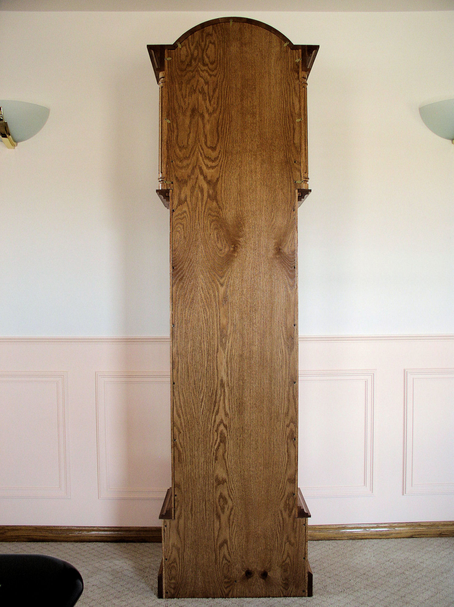
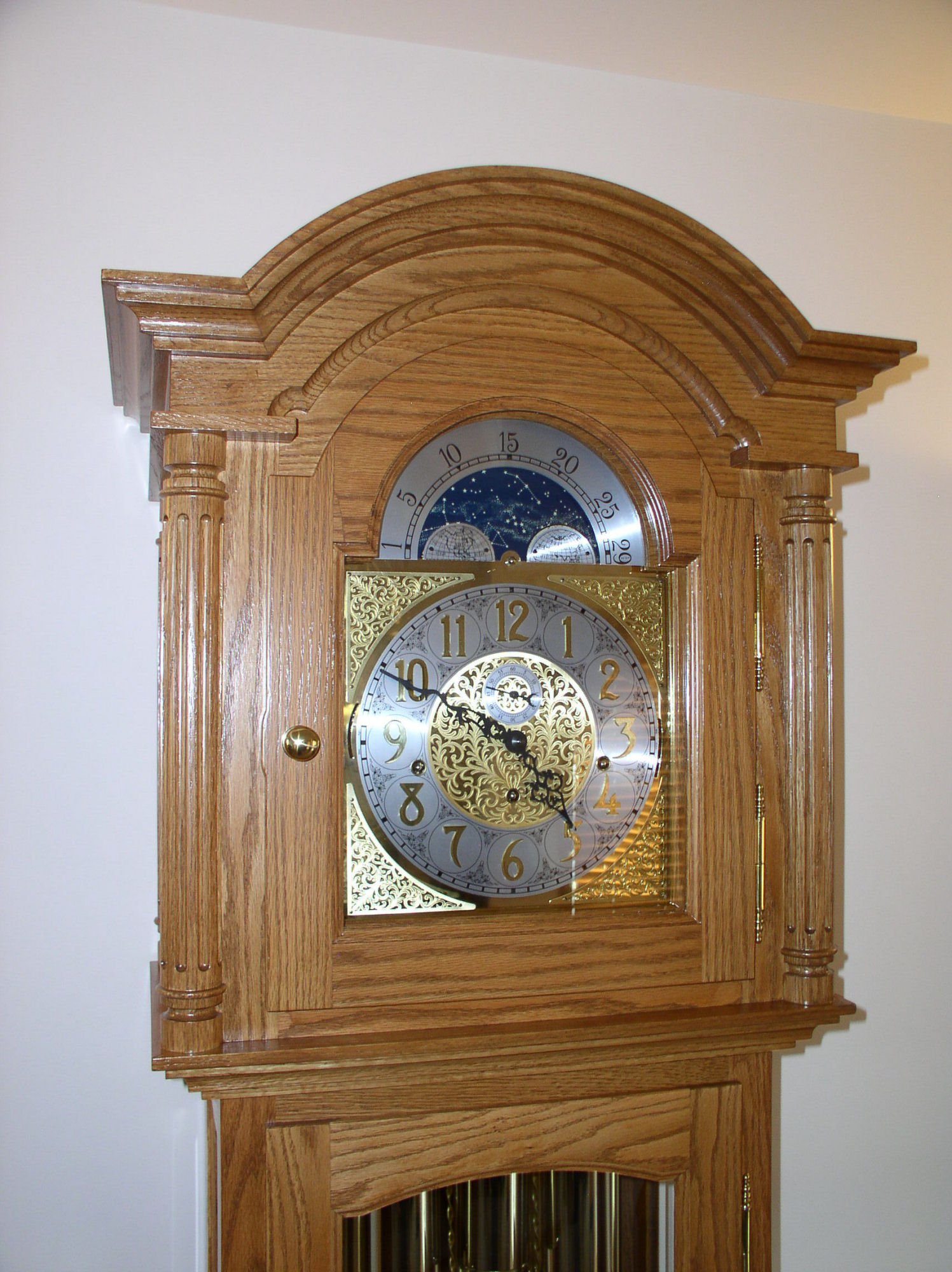
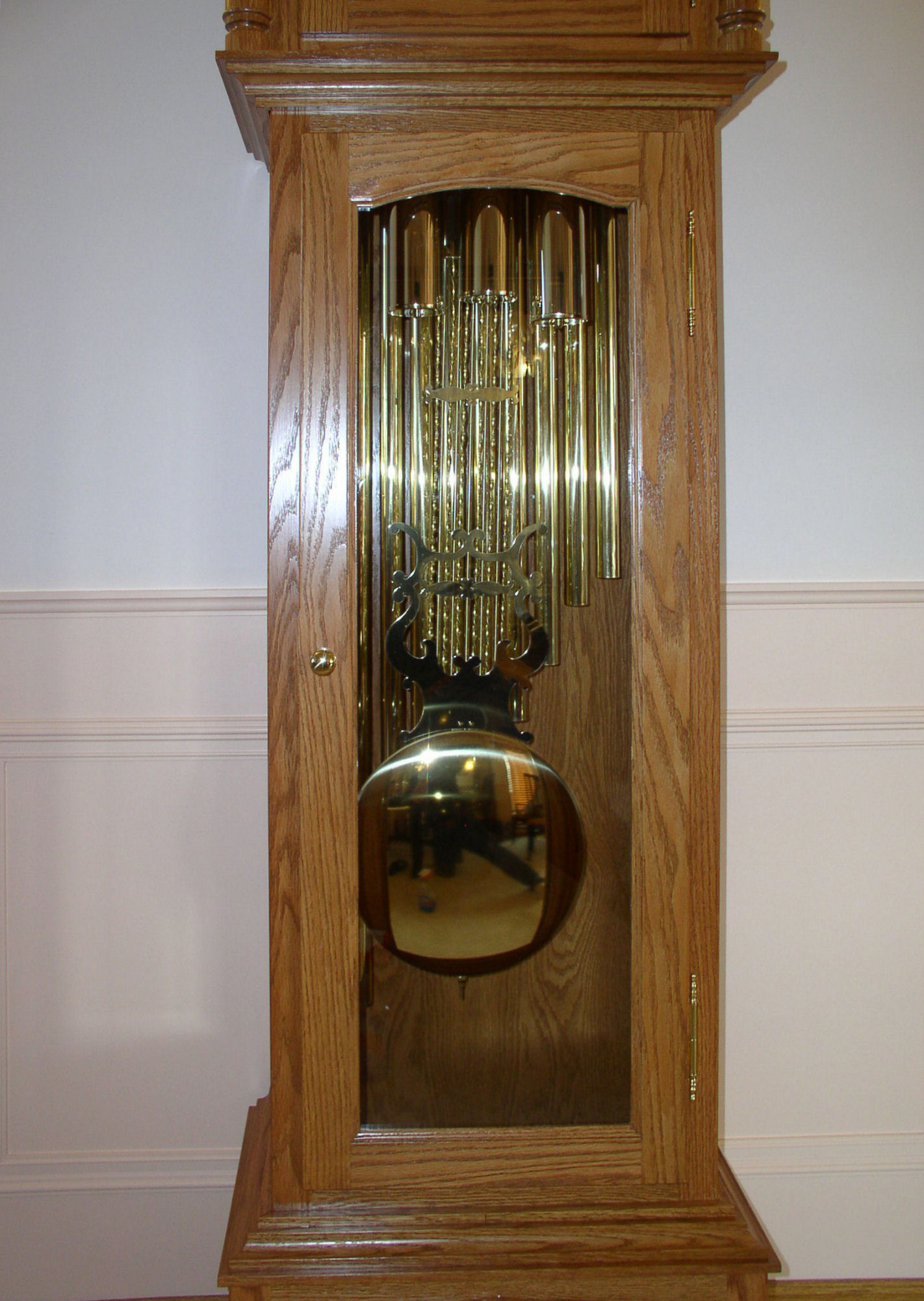
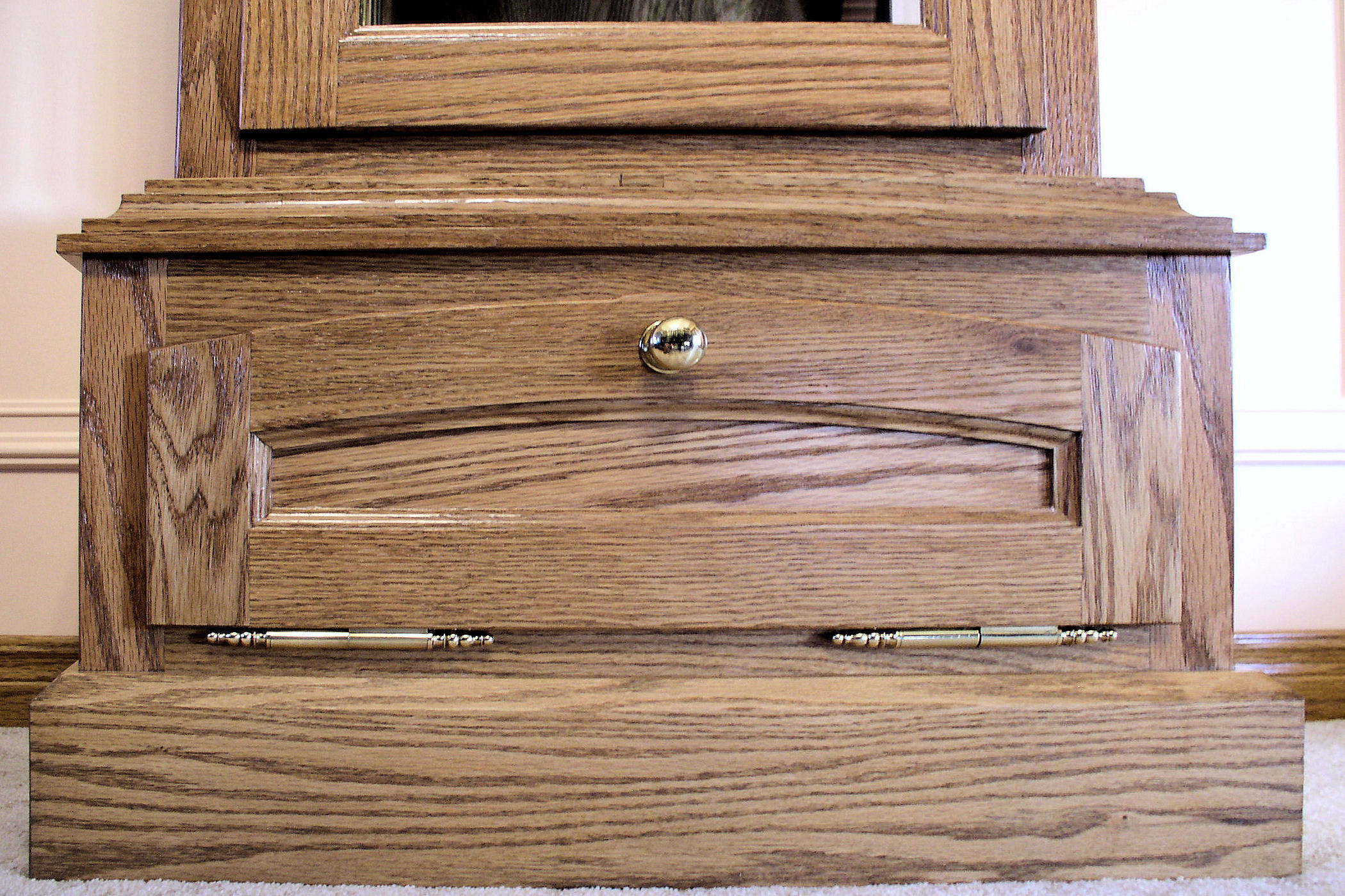
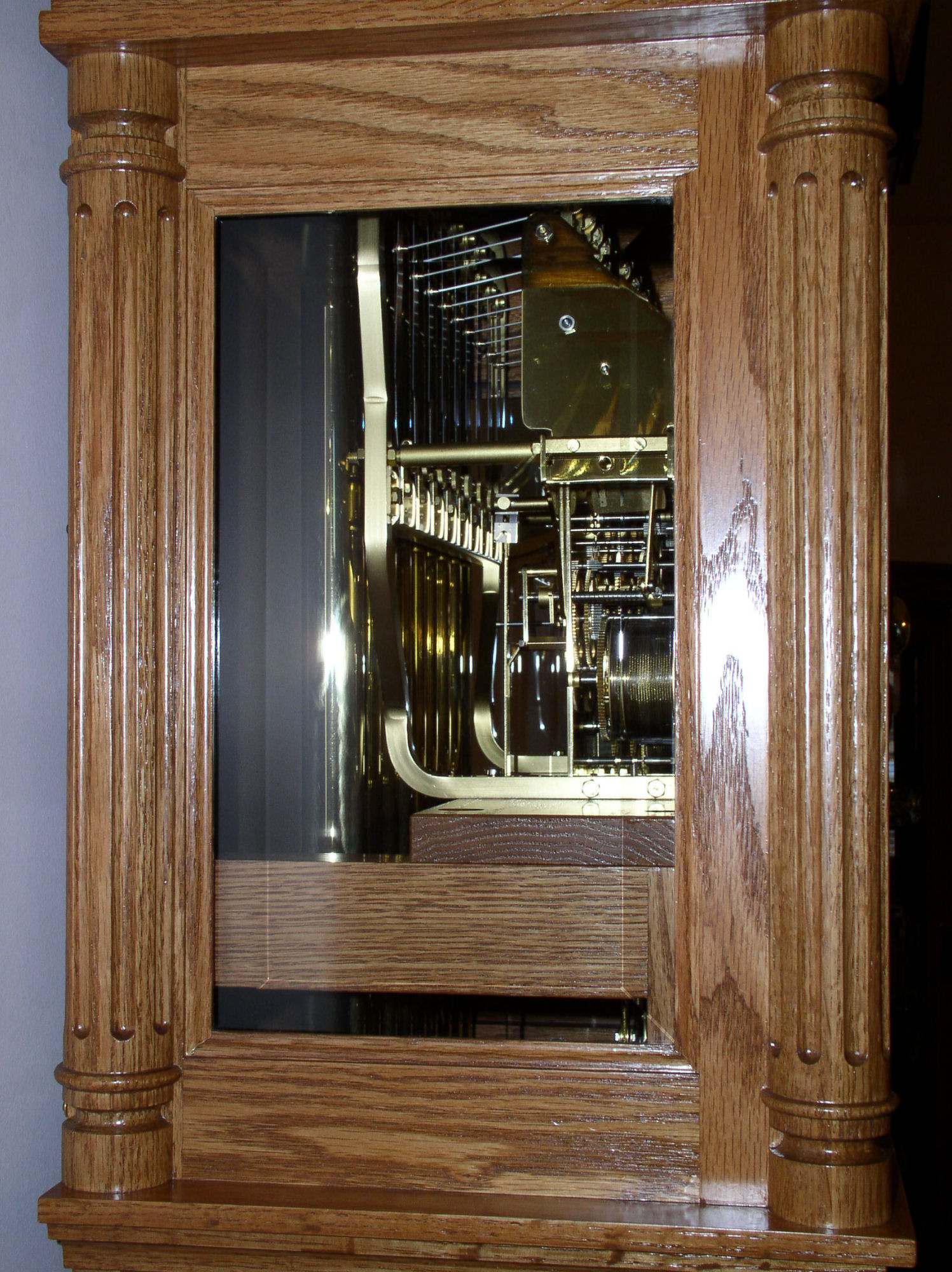
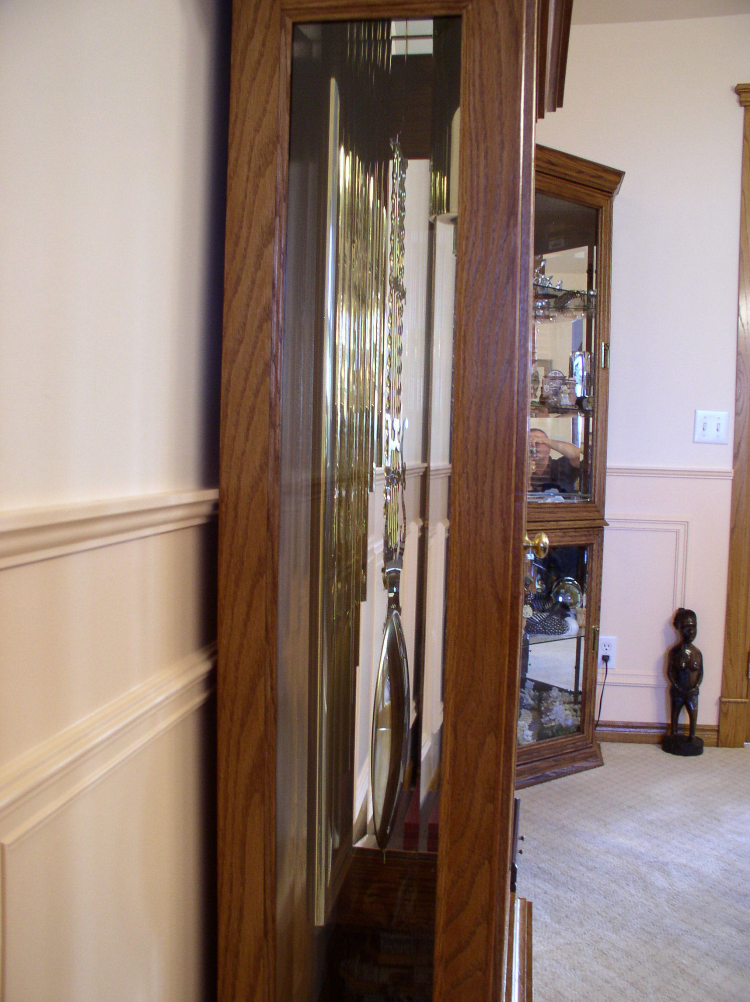
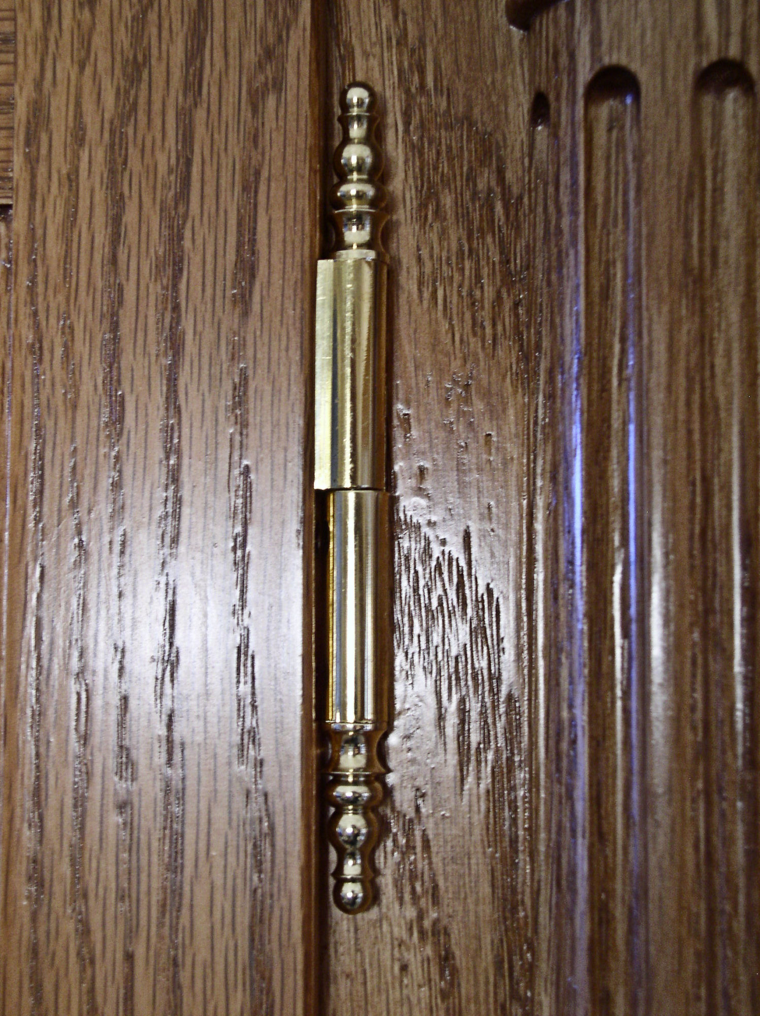
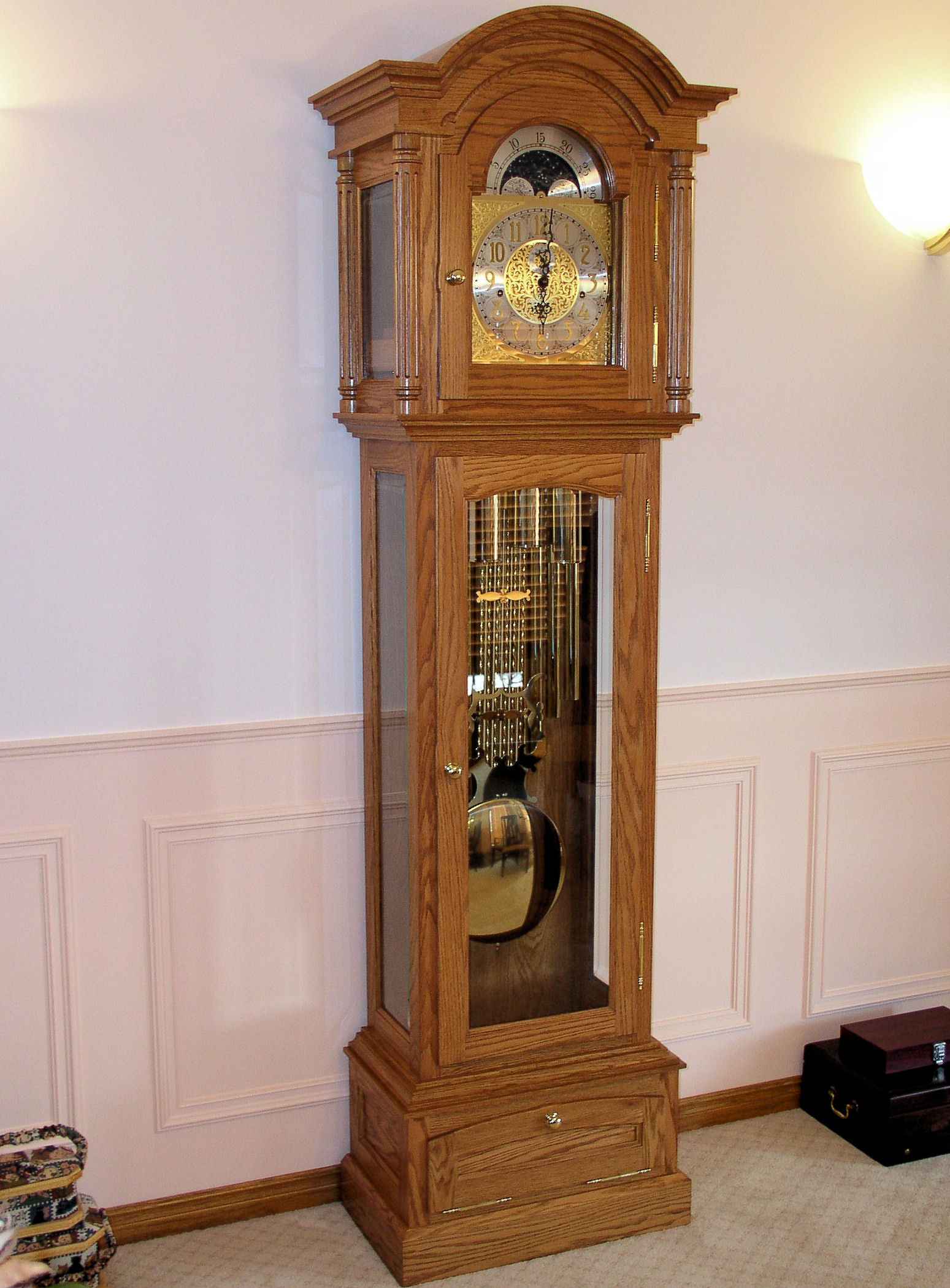
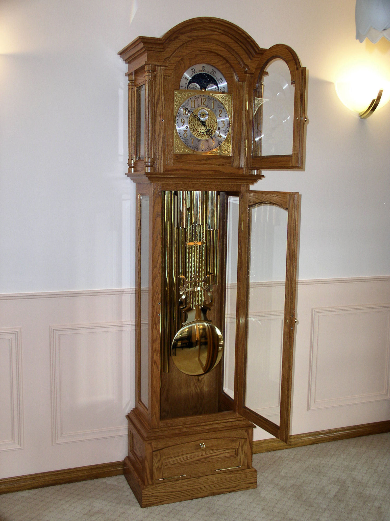
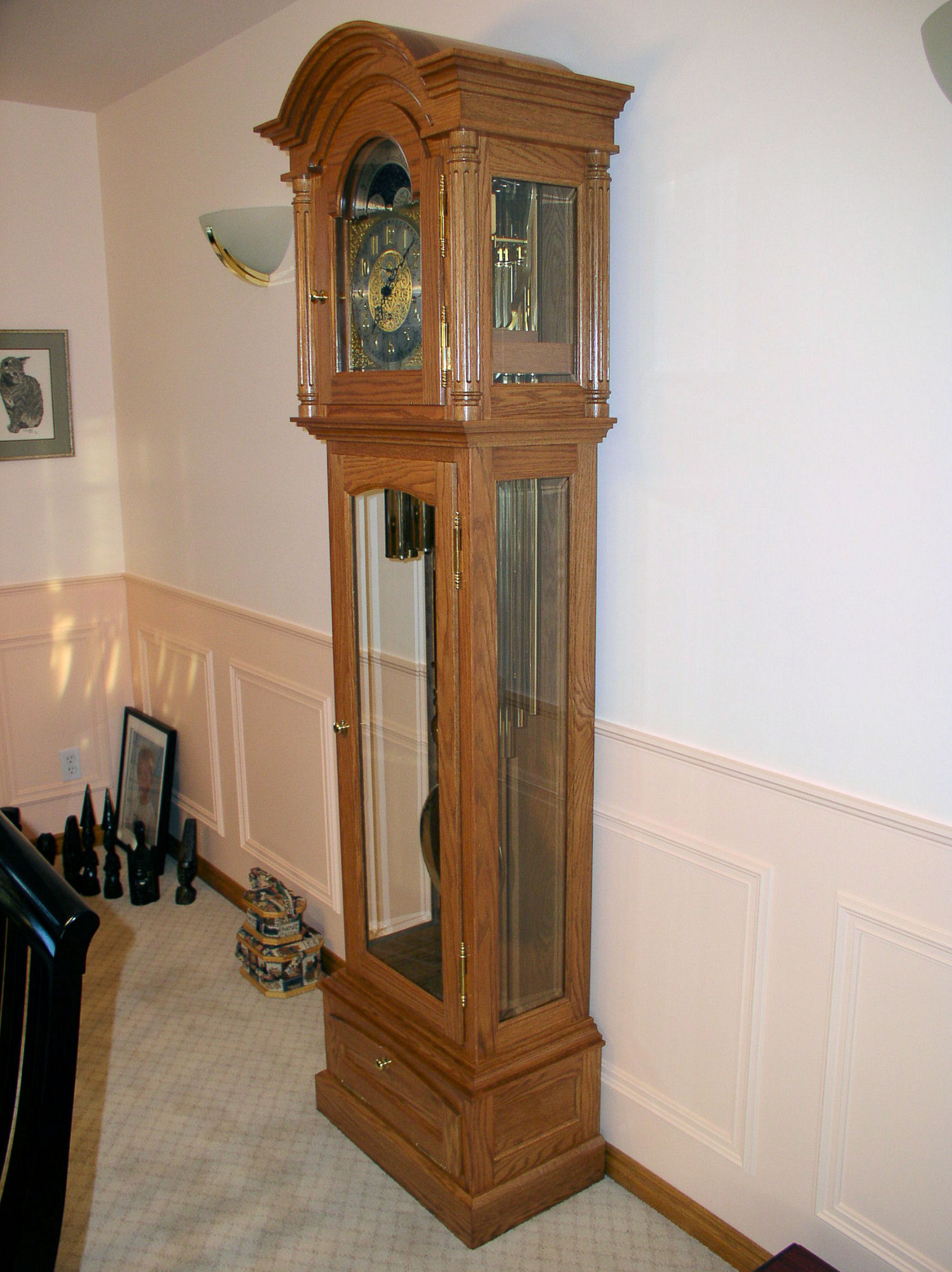
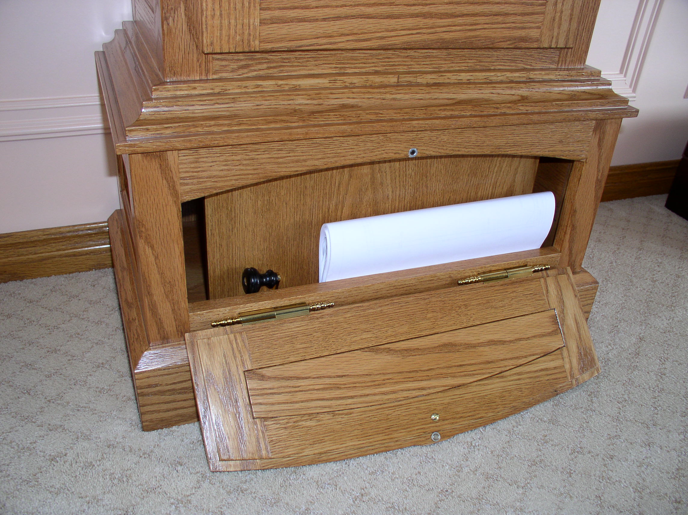